4 testing ai in “voltage” mode, 5 testing ao in “voltage” mode, Testing ai in “voltage” mode – B&B Electronics ZZ24D-NA(NB,NC,ND)-SR - Manual User Manual
Page 73: Testing ao in “voltage” mode, Ee figure 47)
Troubleshooting
Manual Documentation Number: pn7515_ZlinxIO-0712m
67
Figure 47 Digital Output (Sinking driver) wiring
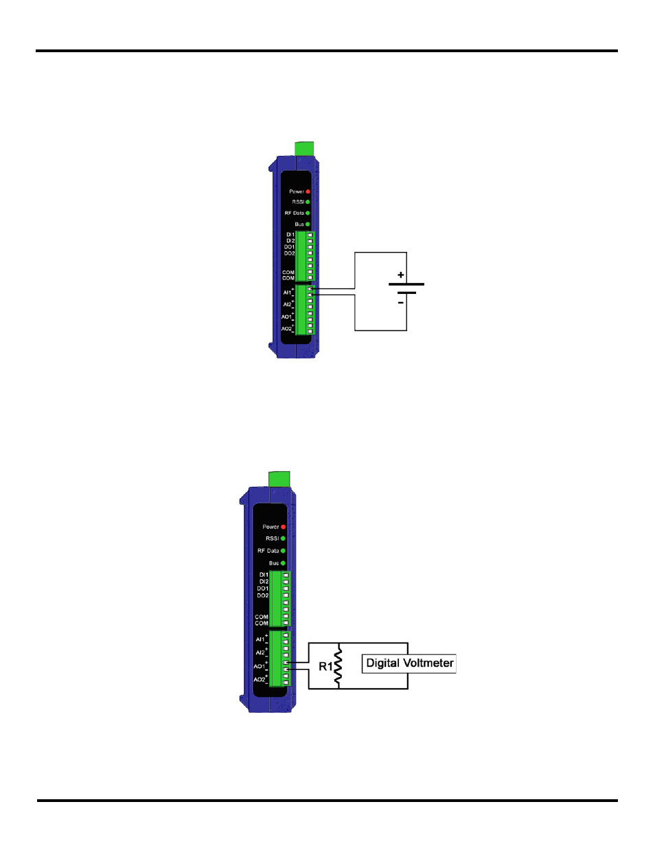
9.1.4 Testing AI in “Voltage” Mode
Connect an AA battery (1.5 VDC) on the AI-1 on System-1 (see Figure 48) and a voltmeter on the corresponding AO-1 on
System-2. Make sure the polarity is correct while connecting the battery. Measure the voltage on the Analog Output on
System-2. It has to indicate 1.5 VDC.
Figure 48 Analog Input wiring
9.1.5 Testing AO in “Voltage” Mode
To test an Analog Output in “voltage” mode the following can be performed. Refer to “Appendix E: Zlinx Wireless I/O Models
and Features” for the list of Analog Output modules. On the corresponding Zlinx Wireless I/O device on System-1 connect an
AO to a voltmeter as shown in the figure below (Figure 49). Supply a voltage signal on the AI side of System-2. Confirm on
System-1 with a voltmeter that the voltage on the corresponding output matches the voltage input.
Figure 49 Analog Output (Sourcing driver) wiring