4 input/output settings, Input/output settings – B&B Electronics ZZ24D-NA(NB,NC,ND)-SR - Manual User Manual
Page 53
Configuration & Operation
Manual Documentation Number: pn7515_ZlinxIO-0712m
47
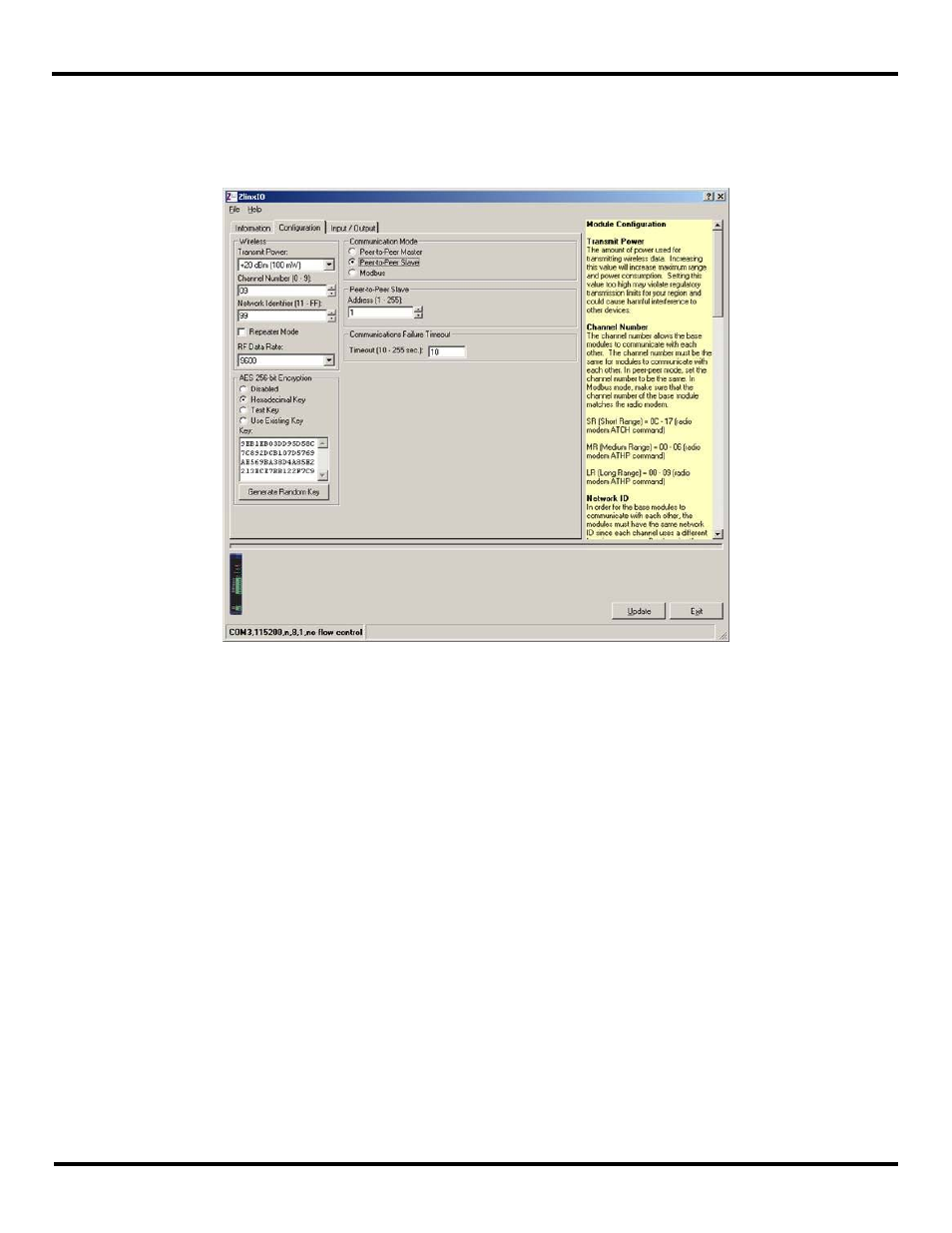
3. Set the Peer-to-Peer Slave address from 1 to 255. Please note the Peer-to-Peer Master address must also match.
4. Communication Failure Timeout. If within the predefined timeframe no data is coming from Peer-to-Peer Master, Slave
interprets it as a communication failure.
Figure40
Peer-to-Peer Slave Configuration
5.1.4 Input/Output Settings
Digital Inputs/Outputs and Analog Inputs/Outputs on Zlinx Wireless I/O modules are configured from the Input/Output tab of
the Zlinx Manager. The first two Digital Inputs on any module can be configured as Discrete inputs or Counter inputs. Any
additional Digital Inputs operate as Discrete inputs only. Counter operation is only functional when the Zlinx Wireless I/O is set
up in Modbus mode. Analog Inputs and outputs can be configured for voltage or current loop operation.
To configure Digital and Analog I/O:
1. Select the Input/Output tab.
- USOPTL4DR-LS - Datasheet (2 pages)
- ZXT9-IOA-KIT - Manual (75 pages)
- ADAM-6066 - Manual (272 pages)
- 855-11619--57 - Datasheet (2 pages)
- 851-10904 - Datasheet (2 pages)
- SS-BLT-100PR - Quick Start Guide (1 page)
- ISOCON-6 - Datasheet (2 pages)
- I-7060 - Manual (64 pages)
- AMU864 - Datasheet (2 pages)
- 714FX6-SC_ST - Manual (154 pages)
- 422LP25R - Datasheet (2 pages)
- ZP9D-115RM-LR - Manual (54 pages)
- EKI-6311GN-EU - Manual (56 pages)
- ZZ24D-NA(NB,NC,ND)-SR - Quick Start Guide (4 pages)
- ESCLP-100 - Manual (23 pages)
- 806-39753 - Datasheet (1 page)
- 485SD9RJ - Datasheet (1 page)
- 712FX4-SC_ST - Manual (154 pages)
- 850-18610 - Manual (18 pages)
- ESW208 Series - Datasheet (2 pages)
- VESR321_ML_SL - Quick Start Guide (3 pages)
- OP10 - Datasheet (1 page)
- RT3G-300_310_320_330_340-W - Configuration Manual (79 pages)
- EIRHP305-T - Datasheet (2 pages)
- EIRSP1 - Datasheet (1 page)
- 422TTL33 - Datasheet (2 pages)
- 485DRCI - Quick Start Guide (2 pages)
- I-7021_P - Datasheet (2 pages)
- NTSA-CAT5E - Datasheet (2 pages)
- 485COSR - Datasheet (2 pages)
- 855-10619--57 - Datasheet (2 pages)
- UH401SL_2KV - Datasheet (2 pages)
- 105FXE-SC(ST)-15-POE - Manual (19 pages)
- 102MC-FL_SC_ST - Manual (23 pages)
- CBL00302 - Datasheet (1 page)
- 850-18100--27 - Datasheet (2 pages)
- 850-10953-DC - Datasheet (2 pages)
- ESR904 - Datasheet (2 pages)
- 308TX-N - Datasheet (3 pages)
- 422LP25N - Datasheet (2 pages)
- 708FX2-SC_ST - Datasheet (3 pages)
- MESR321_SL_ML - Datasheet (2 pages)
- SL2736-698 - Quick Start Guide (8 pages)
- I-7188E Series - Datasheet (1 page)
- ANT-PAD58-19 - Datasheet (1 page)