1 base modules, 2 expansion modules, Base modules – B&B Electronics ZZ24D-NA(NB,NC,ND)-SR - Manual User Manual
Page 22: Expansion modules
Hardware Information
16
Manual Documentation Number: pn7515_ZlinxIO-0712m
3.2.1 Base Modules
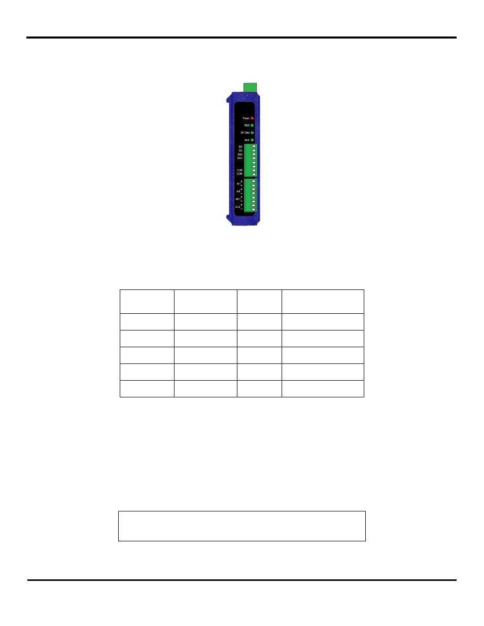
Each Zlinx Wireless I/O system is built around a Base Module. Base Modules provide digital and/or analog I/O, and radio
communications with other Zlinx nodes.
Figure 8
A Typical Base Module (2AI-2AO-2DI-2DO)
Radio options include three frequency bands 2.4 GHz, 900 MHz, and 868 MHz (868 band is applied in Europe and due to the
single-channel band, to prevent excessive interference between radios regulations require radios to not exceed a 10%
transmission duty cycle. This means that the radio can only be transmitting 10% of the time), and three power output/range
categories: Short Range, Medium Range, and Long Range.
Frequency
Band
Range
Category
Indoor
Outdoor
(Line of Sight)
2.4 GHz
Short Range
(SR)
300 ft
1 mile
2.4 GHz
Medium Range
(MR)
600 ft
3 miles
900 MHz
Medium Range
(MR)
1500 ft
7 miles
900 MHz
Long Range
(LR)
1800 ft
25 miles
868 MHz
Long Range
(LR)
1800 ft
25 miles
Figure 9
Radio Type Options and Ranges (with included antennas)
Several different combinations of Digital Inputs (DI), Digital Outputs (DO), Analog Inputs (AI) and Analog Outputs (AO) are
available. For example, the ZZ24D-NA-SR features a combination of two DI’s, two DO’s, two AI’s, and two AO’s in a package
with a short range (SR) 2.4 GHz radio option. Similar models are available with Medium Range (MR) and Long Range (LR)
radio options.
3.2.2 Expansion Modules
Up to six Expansion Modules can be plugged into the Base Module to add more I/O capabilities in any combination needed.
For example, the ZZ-8DO-T Expansion Module provides eight additional Digital Outputs; the ZZ-2AI2AO provides two Analog
Inputs and two Analog Outputs.
NOTE: Refer to “Appendix E: Zlinx Wireless I/O Models and Features” for a list of
Zlinx Wireless I/O models and features
.
Expansion Modules connect to Base Modules by plugging the modules together, engaging the local bus connectors located on
the sides of the boxes. Male plugs on Expansion Modules plug into female connectors on the side of the Base Module or