Appendix e: schematics, E schematics, E.1 dc trip system – Siemens ISGS SG8158-00 User Manual
Page 85
Appendix E: Schematics
Siemens Energy & Automation, Inc.
79
E Schematics
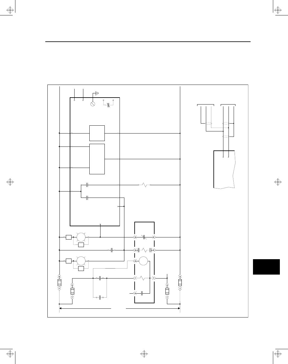
E.1 DC Trip System
The following diagram illustrates a typical connection
scheme for the ISGS relay when using a DC trip system.
Figure E.1 Wiring for DC Trip Systems
52
SRC
LS
88
52T
52a
52a
52b
31
3
1
6
1
4
15
2
1
4
N
P
3
1
4
2
3
1
4
2
Fuse
Fuse
Fuse
Fuse
RES
RES
RES
RES
RG
3
4
CS
C
95C
1
2
CS
T
15
16
12
20
19
49
48
14
21
1
ISGS Relay
11
7
1
8
13
T
rip
Common
Impedance
Source
Impedance
Sense
T
rip 1
T
rip 2
BI
T
rip
Ground
Monitor
PS
IN2
PS
IN1
BI BSW
Monitors
b-contacts
Monitors
a-contacts
and trip coil
T
rip Source
Impedance
Sense Circuit
Power
Supply
(DC-DC)
95C
Optional
Remote
Closing
Optional
RS-485
Communications
+
-
(see below)
Case
Ground
DC
Supply
(Station
Battery)
49
48
Optional
RS-485
Communications
Outgoing
RS-485
Bus
Incoming
RS-485
Bus
Data +
Data +
Data +
Data -
Data -
Data -
Shield
Shield
Key
52a
Aux Switch (open when breaker is open)
52b
Aux Switch (closed when breaker is open)
52T
Opening Solenoid (Trip)
52SRC
Spring Release Solenoid
88
Spring Charging Motor
CS/C
Control Switch/Close
CS/T
Control Switch/T
rip
R
Red Lamp (breaker open)
G
Green Lamp (breaker open)
95C
Interposing Relay
LS
???
Breaker
*Contact is
closed when
relay is out of service
Relay
Disabled*
E
isv3o_1.bk : isv3osch.frm Page 79 Wednesday, August 7, 1996 10:51 AM