Data acquisition, 7 data acquisition – Siemens ISGS SG8158-00 User Manual
Page 49
Data Acquisition
Siemens Energy & Automation, Inc.
43
7 Data Acquisition
The ISGS relay provides several forms of data acquisition
and display to give the user the most comprehensive picture
of the power system. This data includes:
event log for monitoring functions and status changes
trip logs, including date and time of trip
minimum/maximum logs for storing metering data
individual metering data
waveform captures
7.1 Event Log
The event log is a chronological record of the last 127 signifi-
cant events that occur during operation of the relay and is
stored in nonvolatile memory. These events include opera-
tional events, such as enabling or disabling protective ele-
ments; and fault events, such as pickup and trip. Each entry
in the log provides a description of the event and its time (to
nearest millisecond) and date of occurrence.
The event log cannot be viewed through the ISGS relay oper-
ator panel. It can only be viewed after being retrieved through
one of the relay communication ports using either Wisdom or
WinPM software.
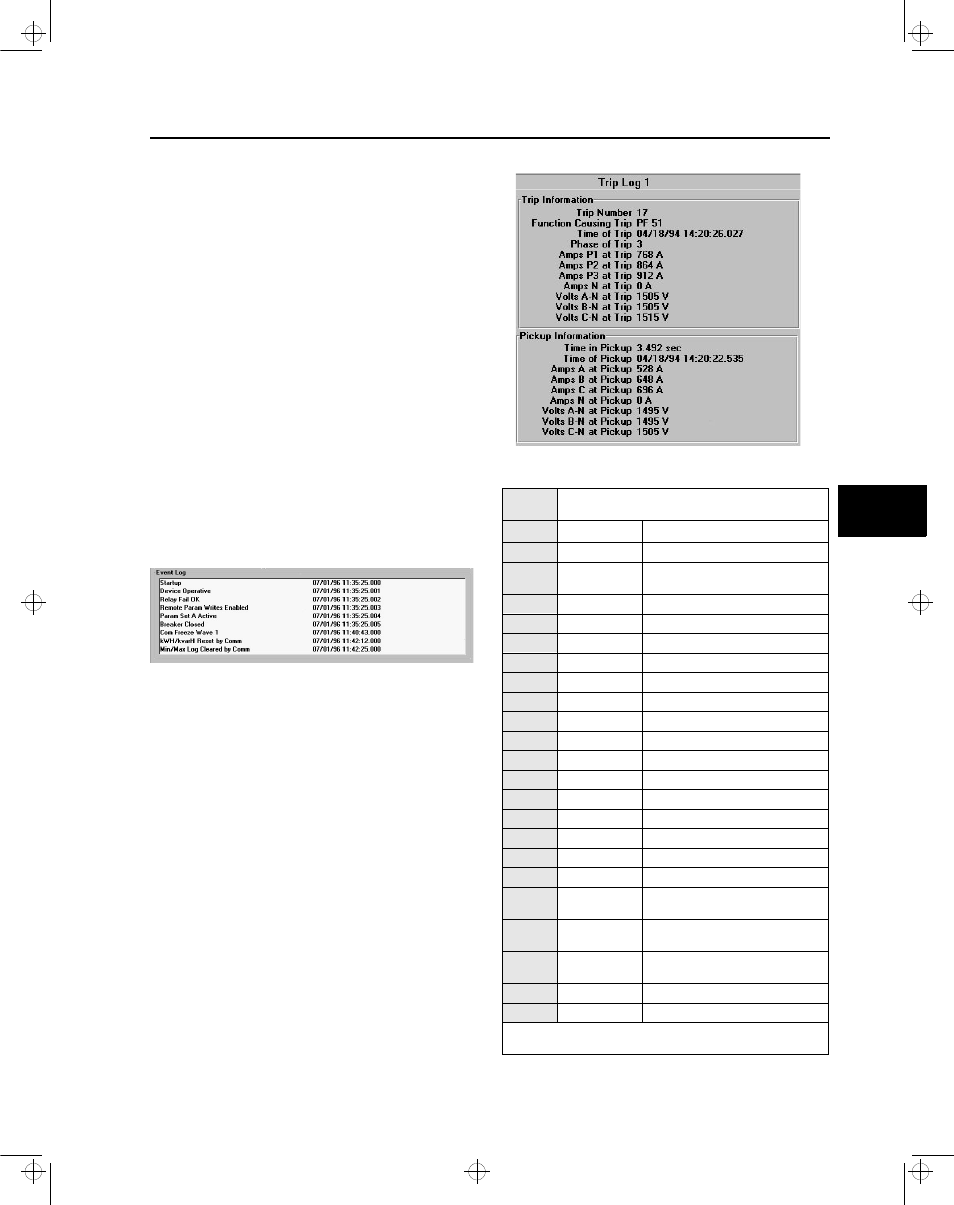
Figure 7.1 Sample Event Log (viewed with Wisdom)
Events that require special attention appear in the event log
in red when displayed on a PC. The entire event log can be
saved to a file (for later viewing or printing) using Wisdom
software. For information on Wisdom software, refer to
Chapter 8.
Whenever the ISGS relay resets, such as when changing
parameter sets or output control actions, the event log is
considered invalid and all events are re-read by communica-
tions.
7.2 Trip Logs
The Trip Logs function stores times and measured data
present at the time of pickup and trip for the last eight trip
events. The information for each trip is stored in its own log.
These eight logs are located at address blocks 5100 through
5800. The most recent trip event is stored under address
5100 and the oldest of the eight trip events is stored in
address 5800. Pressing the Trip Log key takes you directly
to the trip log address block. The first trip to be sensed is the
trip to be logged
Figure 7.2 Sample Trip Log Data Display (from Wisdom)
5100 to
5800
Trip Logs
Address Data
Description
001 Trip Number
Date and event record number
002 Pickup Time
Time of the event to the nearest
millisecond
003 Pickup
The function that picked up
004 Phase
The phase that picked up
005 I1
Current at pickup for phase 1
006 I2
Current at pickup for phase 2
007 I3
Current at pickup for phase 3
008 IN
Ground current at pickup
009 V1
Voltage at pickup phase 1 (1-2*)
010 V2
Voltage at pickup phase 2 (2-3*)
011 V3
Voltage at pickup phase 3 (3-1*)
012 Trip
The function that caused the trip
013 Phase
The phase that caused the trip
014 I1
Secondary current at trip for phase 1
015 I2
Secondary current at trip for phase 2
016 I3
Secondary current at trip for phase 3
017 IN
Secondary Ground current at trip
018 V1
Secondary voltage at trip phase 1
(1-2*)
019 V2
Secondary voltage at trip phase 2
(2-3*)
020 V3
Secondary voltage at trip phase 3
(3-1*)
021 TinPU
Total time in pickup
022 End of Table
Last entry in this log
* If VTs are connected line-to-line (see address 1202,
Section 4.5), the line-to-line voltage is displayed.
7
isv3o_1.bk : isv3odaq.frm Page 43 Wednesday, August 7, 1996 10:51 AM