Control & communications, 6 control & communications – Siemens ISGS SG8158-00 User Manual
Page 37
Control & Communications
Siemens Energy & Automation, Inc.
31
6 Control & Communications
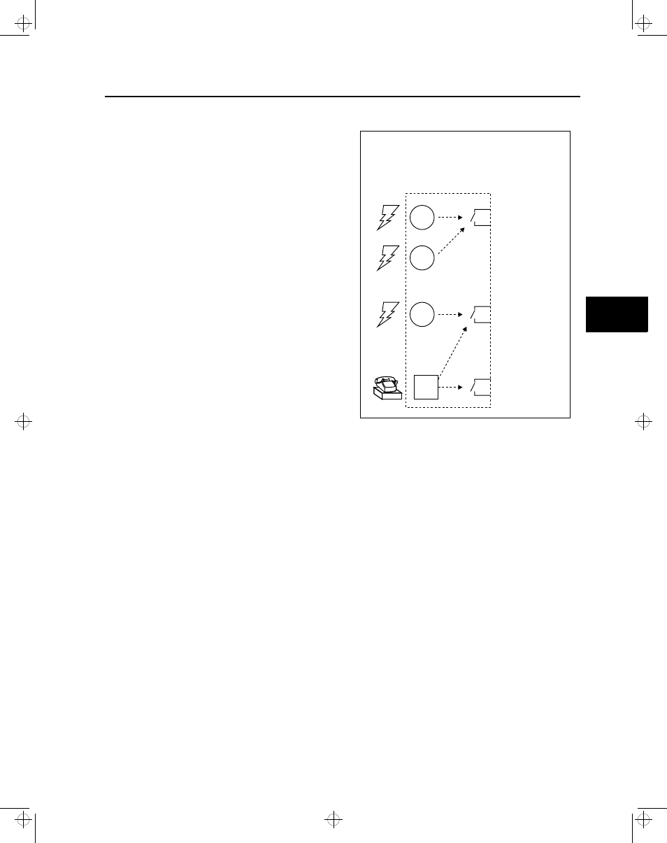
6.1 Matrixing Events to Outputs
One of the powerful functions of the ISGS relay is its ability to
send control outputs based on inputs from the real world.
This process of assigning various outputs to various inputs is
called matrixing. Utilities in Europe call this marshalling. Since
most customers in America are not familiar with this term and
because the word configuring is used in too many other con-
texts, we use the more specific word matrixing. The inputs
that can be used to control outputs can be binary (on/off)
inputs and communication events. The binary inputs deter-
mine if a certain type of protection is being violated and can
close a trip contact or binary output based on the intelligence
of the relay. The outputs can be trip contacts or binary out-
puts. Figure 6.1 shows in general form how the outputs can
be controlled by various inputs. The outputs can also be
controlled by a command from an external communication
device on the network; this input is called a Communication
Event. The ISGS relay offers four binary inputs (BI 1, BI 2,
BI 3, and BI 4), two binary outputs (BO 1, BO 2), and three
trip contacts (Trip 1, Trip 2, and Trip 3). Matrixing is used for
blocking and event-driven functions as well as for binary
input and setpoint functions.
A physical input is a hardware connection to the relay such
as binary input 1 (BI 1). A logical input is an input to a func-
tion internal to the relay such as the blocking input for under-
voltage (protective function, 27) (see Section 5.12). The
logical input can only be activated if it is matrixed to the
physical input. Connecting the physical input BI 1 to the logi-
cal input for function number 27 allows BI 1 to block PF27
when active. Up to 10 logical inputs can be matrixed to each
output contact.
A physical output is a trip contact or binary output (BO). A
logical output is the output of a function internal to the relay
such us Pickup, which is active when function 27 is in
pickup. Connecting a logical output to a physical output
allows function 27 to trip (actuate a contact). Up to 20 logical
outputs can be matrixed to each output contact.
Note: Matrixing includes defining which protective
functions actuate an output contact, and
which output contact they actuate. Matching
the output connections of the relay with the
wiring connections of the protective circuit,
including the connections to the circuit
breaker, is extremely important. If the matrix-
ing of the ISGS relay is changed, double-
check the wiring of the protective circuit, and
always test that the operation of a protective
function results in the circuit breaker tripping.
Without matrixing, an event will cause an entry in the Event
Log, but nothing will happen with the outputs and no control
activity will occur. With matrixing, an event can cause the
relay to trip a breaker (for example) as well as causing an
entry in the Event Log.
Figure 6.1 Matrixing Inputs to Outputs
Events
Outputs
Output Contact
or
Trip Contact
or
Binary Output
Event 1
Event 2
Event 3
Comm
Event
50HS
27
50N
Output 1
Output 2
Output 3
6
isv3o_1.bk : isv3oc&c.frm Page 31 Wednesday, August 7, 1996 10:51 AM