User interface, 3 user interface – Siemens ISGS SG8158-00 User Manual
Page 15
User Interface
Siemens Energy & Automation, Inc.
9
3 User Interface
Operation, parameter selection, and control of the ISGS relay
are performed using the front panel controls and indicators.
They consist of a 26-key membrane keypad, a 2-line by
16-character liquid crystal display (LCD), three light-emitting
diodes (LEDs), and the front port.
3.1 Keypad
The relay can be controlled via the keypad, the front port, or
the optional rear port. This manual covers only keypad oper-
ations. For information about communicating with the ISGS
relay via the data ports, refer to the documentation supplied
with the communications software (WinPM or Wisdom).
The ISGS relay keypad allows access to any relay informa-
tion or function for display or parameter changes where
applicable. The keypad consists of 26 keys. Table 3.1 pro-
vides a detailed description of each key type.
To access relay information or functions for display or modifi-
cation, use the Arrow keys to scroll through relay addresses
or use the Direct Addr key and the specific address number
to go directly to the information or function.
Use the Double Arrow keys to scroll through the address
blocks and use the Single Arrow keys to scroll within an
address block.
3.2 Indicators
The indicators on the front panel display consist of three
LEDs and a two-line LCD.
3.2.1
LEDs
The LED indicators are used to provide general status infor-
mation, which alerts the operator to an event or problem and
prompts the operator to use the LCD to review the logs for
more detailed information. The three LEDs and their func-
tions are listed below.
Both the Pickup and the System LED operate automatically
and do not require a reset.
The System LED remains on as long as power is applied
and the relay is functioning properly.
The Pickup LED is illuminated as long as a protective
function is in pickup.
LED
Color
Function
System Green
Denotes the relay is operating properly
(always on when relay is in service).
Pickup
Red
Denotes a protective function is in
pickup.
Trip
Red
Denotes a protective function or
remote command has initiated a trip.
.
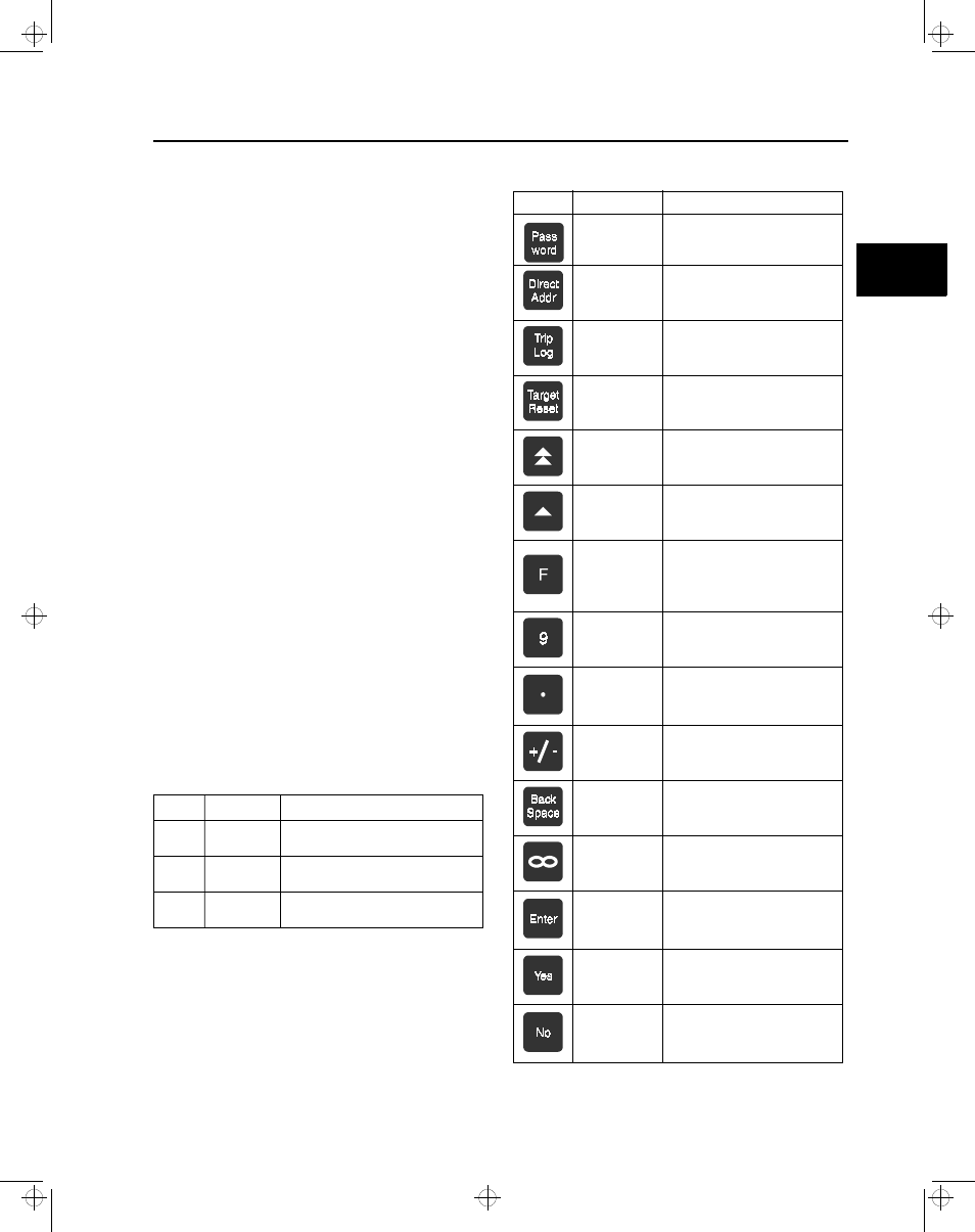
Key
Name
Function
Password
Accesses the password function,
which is required for programming
relay settings.
l
Direct Addr
Allows direct entry of addresses.
Trip Log
Displays the trip log.
Target Reset
Resets the Trip LED.
Double Arrow
Scrolls through the address
blocks.
Single Arrow
Scrolls through the addresses
within an address block.
F
Saves new settings when followed
by Enter, enters or exits subad-
dress level, or switches to alter-
nate parameter set when followed
by 1 or 2 and Enter.
Numeric
Used to enter an address number
after pressing Direct Addr, or to
enter a numeric setting.
Decimal Point
Indicates a decimal point or the
separation between month, day,
and year, or between hours, min-
utes, and seconds.
Plus/Minus
Toggles between positive and
negative values.
Backspace
Deletes one character to the left or
selects backwards.
Infinity
Programs the setting to the high-
est possible value.
Enter
Chooses the setting option, enters
a setting value, or confirms the
address entered after pressing
Direct Addr.
Yes
Accepts the displayed setting, or
replies yes to the displayed
prompt.
No
Rejects the displayed setting,
allows entry of a numeric setting,
replies No to the displayed
prompt, or selects forward.
Table 3.1 Front Panel Keys
3
isv3o_1.bk : isv3ousr.frm Page 9 Wednesday, August 7, 1996 10:51 AM