Hardware configuration – Siemens ISGS SG8158-00 User Manual
Page 22
Hardware Configuration
16
Siemens Energy & Automation, Inc.
4.2 Device Configuration
The Device Configuration function allows you to set up the
ISGS relay to match line frequency, phase sequence, and
breaker connection settings of your system.
The frequency parameter (1002) must be set to the nominal
frequency of your system. Phase sequence (1003) selects
the phase sequence of your system as it enters the ISGS
relay. The breaker connection parameter (1004) selects the
trip contact that your breaker is connected to. Many func-
tions use this parameter to determine if the device is
attempting to open the breaker. Breaker failure can be initi-
ated by either one of the three trips (if the Breaker Failure
function is enabled). The default is set to Trip 1.
1000 Device Configuration
Address Parameter
Options
1002 Frequency
50Hz or 60Hz
1003 Phase Sequence
123 (ABC) or 132 (ACB)
1004 Breaker
Connection
Trip 1, Trip 2, Trip 3, Trip 1 & 2,
Trip 1 & 3, Trip 2 & 3, or
Trip 1 & 2 & 3
1005 Trip Time
0.01-32.00 s (0.01 s steps)
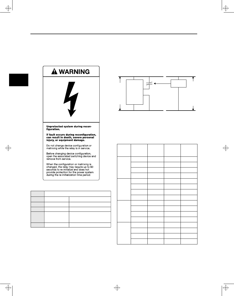
4.3 Setting Binary Input Voltages
Binary inputs are jumpered to correspond to the auxiliary
supply voltage of the relay in which they are installed. The
inputs will correctly respond to DC or AC depending on the
jumpering. The jumpers can be placed to allow the inputs to
work with any of the available voltages, independent of the
auxiliary supply voltage. Refer to Figure 4.5 and Table 4.1.
Figure 4.4 Binary Inputs Independent of Supply Voltage
Table 4.1 lists the possible jumper positions for setting
binary input voltages. The numbers in this table each refer to
a pin from and to which a jumper can be moved.
h
Table 4.1 Jumper Positions
Voltage
Supply
BI 1
Terminals
21/22
BI 2
Terminals
23/22
BI 3
Terminals
25/26
BI 4
Terminals
27/28
48 V
X111-X112 X23-X22
X34-X35
X46-X47
X13-X14
X25-X26
X37-X38
X49-X50
X16-X17
X28-X29
X40-X41
X52-X53
X19-X20
X31-X32
X43-X44
X55-X56
125 V
(Default)
X111-X112 X23-X22
X34-X35
X46-X47
X13-X14
X25-X26
X37-X38
X49-X50
X17-X18
X29-X30
X41-X42
X53-X54
X19-X20
X31-X32
X43-X44
X55-X56
120 VAC X110-X111 X24-X23
X35-X36
X47-X48
X14-X15
X26-X27
X38-X39
X50-X51
X17-X18
X29-X30
X41-X42
X53-X54
X20-X21
X32-X33
X44-X45
X56-X57
250 VDC X111-X112 X23-X22
X34-X35
X46-X47
X14-X15
X26-X27
X38-X39
X50-X51
X17-X18
X29-X30
X41-X42
X53-X54
X19-X20
X31-X32
X43-X44
X55-X56
125 VDC Bus
120 V
AC Source
to be Monitored
120 VAC
Aux Relay
13
12
21
22
ISGS
Relay
BI 1
4
isv3o_1.bk : isv3ohw.frm Page 16 Wednesday, August 7, 1996 10:51 AM