Installation, Isgs – Siemens ISGS SG8158-00 User Manual
Page 13
Installation
Siemens Energy & Automation, Inc.
7
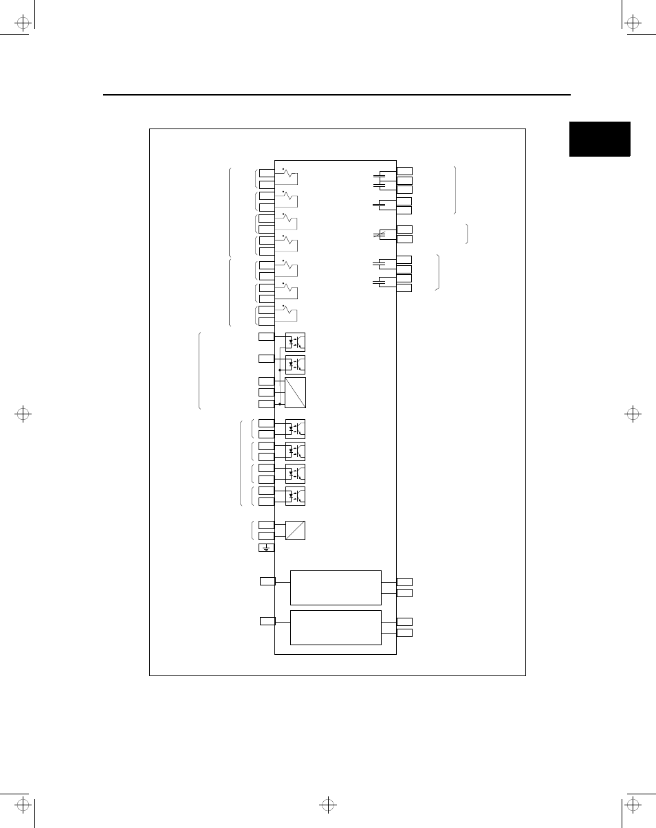
Figure 2.5 Internal Connections
Note: The relay disabled contact should be wired to plant-wide distributed control system or external alarm.
9
3
41
31
33
29
2
Trip 1
Trip Common
Relay Disabled 1
Relay Disabled
Alarm Contact
Relay Disabled 2
Trip 2
Trip 3
19
32
34
30
11
49
(2)
50
(7)
1
20
5
43
7
45
14
21
15
23
17
25
16
27
13
10
4
42
6
44
8
46
22
24
18
26
28
12
48
(3)
DC
DC
RS-485 SEAbus
RS-232
Front Panel
VT 1+
CT 1-1
CT 2-1
CT 3-1
CT N-1
CT 1-2
CT 2-2
CT 3-2
CT N-2
VT 2+
VT 3+
VT 1-
VT 2-
VT 3-
BI B Switch
BI Trip
Impedance Source
Breaker and
Trip Source
Monitor
Impedance Sense
Ground Monitor
+
+
+
+
+
-
-
-
-
-
1
2
3
4
Binary
Input
Current
Input
Voltage
Input
V
H
Power
Supply
Communications
In
Communications
Out
BO 1
BO 2
Trip
Relays
Binary
Outputs
Data +
RxD
Data -
TxD
Reference
Reference
Ground
ISGS
2
isv3o_1.bk : isv3oins.frm Page 7 Wednesday, August 7, 1996 10:51 AM