Protective function configuration – Siemens ISGS SG8158-00 User Manual
Page 35
Protective Function Configuration
Siemens Energy & Automation, Inc.
29
The 50BF Breaker Failure function can be enabled and dis-
abled (2801). When enabled, the protective function begins
monitoring the current flow in the circuit following a trip com-
mand by the relay. Simultaneously, the protective function
starts a timer. If the current flow does not drop below the
pickup value specified (2802) and before the set time delay
(2804) has elapsed, a breaker failure is assumed. At this
point, another trip command can be issued to a different
breaker (via a different output ocntact if available).
The condition of a breaker failure trip depend on the method
chosen, the value of the current after the time has run out,
and the position of the a and b switches.
The range of the pickup value (2802) is based on the sec-
ondary phase CT rating and is in secondary amperes.
The time delay (2804) represents the time between pickup
and trip. The delay can be adjusted from 8 to 254 line cycles
of delay. The function operates if it remains in pickup for
longer than the time delay.
Breaker failure protection monitors the current flow only fol-
lowing a trip by the contact identified at address 1004 (see
Section 4.2). This is the contact matrixed to the overcurrent
protection.
Breaker position is sensed through dedicated binary inputs
that monitor the 52a and 52b switches on the breaker mech-
anism (breaker mounted). The 52a and 52b switches have a
total of four possible position combinations which can be
decoded as illustrated in Table 5.3. The 52a and 52b
switches referred to are those which traditionally provide indi-
cation of circuit breaker position (52b) and trip coil continuity
(52a). All error reporting can be enabled and disabled, and
the actions to be taken are configurable. Refer to
Section 6.6.
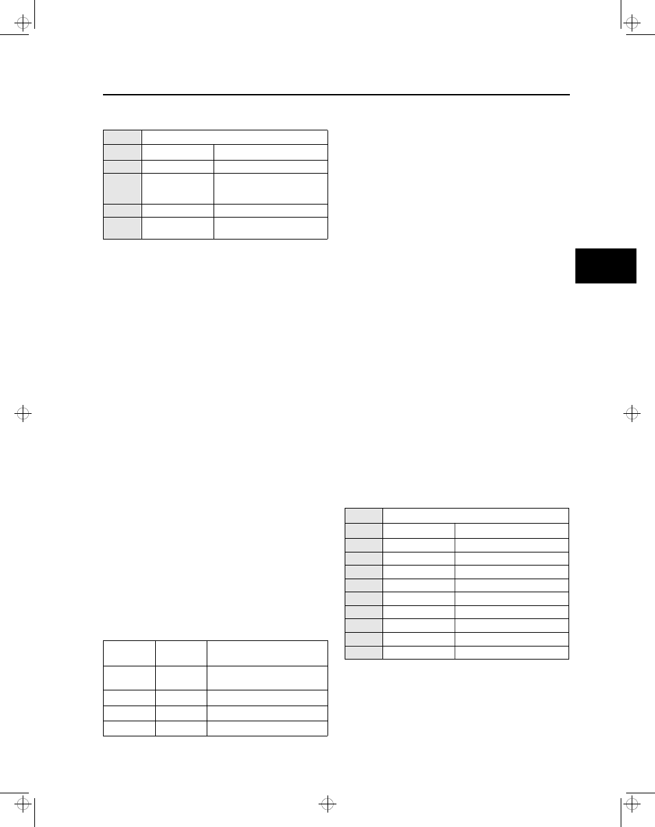
2800 50BF Breaker Failure
Address Parameter
Option
2801 Function
Enabled or Disabled
2802 Pickup
5 A CTs: 0.25-5 A
1 A CTs: 0.05-1 A
(0.01 A steps)
2804 Delay
8-254 cycles
2805 Check
current, breaker opened,
current or breaker opened
Table 5.3 52a and 52b Switches Decoding
52a Switch
Position
52b Switch
Position
Condition Registered
Open
Open
Trip Coil Continuity Error, or
Breaker Withdrawn
Open
Closed
Circuit Breaker Open
Closed
Open
Breaker Closed
Closed
Closed
Circuit Breaker Mechanism Error
Exceptions to the normal operating conditions include the
presence of push-to-test switches across either the
a-switch, b-switch, or both. A push-to-test switch across the
b-switch will produce a false indication of a breaker mecha-
nism error when the breaker is actually closed. A push-to
test switch across the a-switch (and hence across the trip
solenoid) will produce a false indication of a breaker mecha-
nism error when the breaker is actually closed.
The Breaker Mechanism function (8305), when enabled,
senses an error in the mechanism that controls the position
of one or both switches (breaker mechanism error), causes
an action to be taken, and an event to be logged if the
switches are ever both closed for more than 100 ms. No
other time delay is implemented. When this function detects
an error, it is considered to be in pickup until the condition is
no longer present.
The ISGS relay considers the b-switch to be more reliable. If
it senses the switches both open at the same time, the
breaker is considered to have a trip coil continuity error or to
be withdrawn. The 52a switch closed and the 52b switch
open are interpreted as a closed breaker. If the relay senses
the 52a switch open and the 52b switch closed, the
breaker is considered to be open. Refer also to Table 5.3.
5.18 Demand Setpoints
The ISGS relay is capable of activating outputs and sending
events when predefined demand calculations exceed the set
thresholds. These setpoints can be enabled or disabled and
are capable of activating any output. Measurement and set-
point parameters in address block 3100 set the alarm report-
ing threshold for the ISGS relay.
The Demand Parameters function selects the time periods
for demand calculations performed by the relay and allows
the user to enable overcurrent demand and kilowatt demand
protection.
Demand intervals (periods) are set to 15, 30, or 60 minutes
(3101). Demand calculations are updated at the end of every
demand period.
Demand period calculations can begin on the hour or at any
quarter hour afterwards. The intervals are indicated as 0, 15,
30, or 45 minutes and are set in the Sync Time parameter
(3102).
3100 Demand Parameters
Address Parameter
Option
3101 Demand Interval
15, 30, 60 minutes
3102 Sync Time
0, 15, 30, or 45 after hour
3103 Subperiods 60
1, 2, 3, 4, 6, or 12
3104 Subperiods 30
1, 2, 3, or 6
3105 Subperiods 15
1 or 3
3106 I Av Dmd Function
Enabled or Disabled
3107 I Av Dmd Pickup
0-9999 A (1 A steps)
3108 KW Dmd Function
Enabled or Disabled
3109 KW Dmd Pickup
0-999,999 kW (1 kW steps)
5
isv3o_1.bk : isv3opro.frm Page 29 Wednesday, August 7, 1996 10:51 AM