Appendix g: interface connector pinouts, Rs-422 serial, Uni-directional parallel – GCC Printers Elite 12ppm User Manual
Page 173: Interface connector pinouts
G-1
Appendix G: Interface connector pinouts
Use the following pinouts and descriptions of the various printer interface connectors if
you need to purchase or make a new cable.
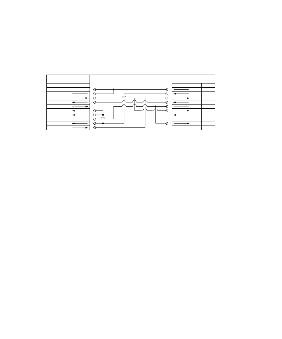
RS-422 Serial:
IBM PC/XT (P1)
25 PIN SERIAL PORT
SIGNAL
PIN
DIRECTION
SHELL
CH. GND
1
TXD
2
RXD
3
RTS
4
CTS
5
DSR
6
SIG.GND
7
DCD
8
DTR
20
PIN
SHELL
1
2
3
4
5
6
7
8
HSKO
HSKI
TXDB-
SIG.GND
RXDB-
TXDB+
NC
RXDB+
SIGNAL
DIRECTION
PRINTER (P2)
MINI-DIN 8
BRAIDED SHIELD
NC
NC
NC
Uni-directional Parallel
PIN
SIGNAL
DESCRIPTION
DIRECTION
1
/STROBE
Data Strobe
In to Printer
2
D1
Data Bit 1
In
3
D2
Data Bit 2
In
4
D3
Data Bit 3
In
5
D4
Data Bit 4
In
6
D5
Data Bit 5
In
7
D6
Data Bit 6
In
8
D7
Data Bit 7
In
9
D8
Data Bit 8
In
10
/ACK
Acknowledge
Out from Printer
11
BUSY
Busy
Out
12
PERROR
Paper Empty
Out
13
SELECT
Select Out
Out
14
/AUTOFD
Not Used
In
15
NC
Not Used
16
GND
Signal Ground