Installing the hmi module – IDEC MicroSmart User Manual
Page 97
3: I
NSTALLATION
AND
W
IRING
« FC4A M
ICRO
S
MART
U
SER
’
S
M
ANUAL
»
3-3
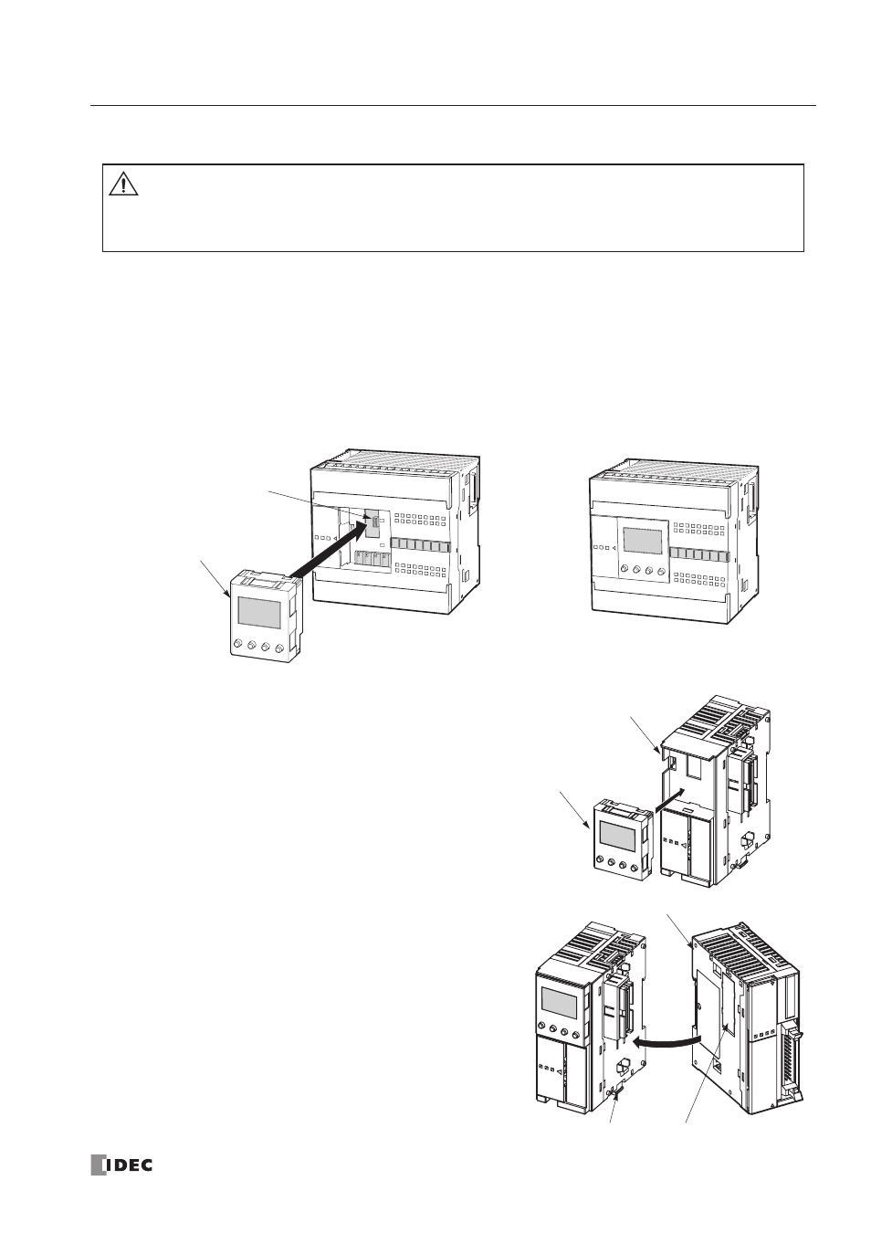
Installing the HMI Module
The optional HMI module (FC4A-PH1) can mount on any all-in-one type CPU module, and also on the HMI base module
mounted next to any slim type CPU module. For specifications of the HMI module, see page 2-60. For details about oper-
ating the HMI module, see page 5-32.
All-in-One Type
1. Remove the HMI connector cover from the CPU module. Locate the HMI connector inside the CPU module.
2. Push the HMI module into the HMI module connector in the CPU module until the latch clicks.
Slim Type
1. When using the HMI module with the slim type CPU mod-
ule, prepare the optional HMI base module (FC4A-HPH1).
See page 2-61.
2. Locate the HMI connector inside the HMI base module.
Push the HMI module into the HMI connector in the HMI
base module until the latch clicks.
3. Remove the communication connector cover from the slim
type CPU module. See page 3-6.
4. Place the HMI base module and CPU module side by side.
With the communication connectors aligned correctly and
the blue unlatch button in the down position, press the HMI
base module and CPU module together until the latches
click to attach the modules together firmly. If the unlatch
button is in the up position, push down the button to engage
the latches.
Caution
• Turn off the power to the
MicroSmart
before installing or removing the HMI module to prevent
electrical shocks.
• Do not touch the connector pins with hand, otherwise electrostatic discharge may damage the
internal elements.
HMI Module
HMI Connector
Unlatch Button
Communication Connector Cover
Slim Type CPU Module
HMI Base Module
HMI Module