IDEC MicroSmart User Manual
Page 37
2: M
ODULE
S
PECIFICATIONS
« FC4A M
ICRO
S
MART
U
SER
’
S
M
ANUAL
»
2-17
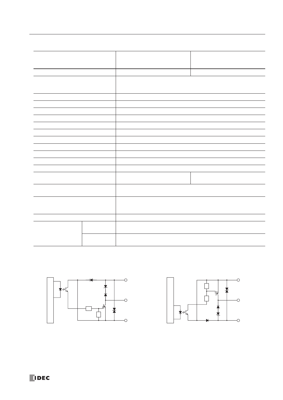
Transistor Sink and Source Output Specifications (Slim Type CPU Module)
Output Internal Circuit
CPU Module
FC4A-D20K3
FC4A-D20RK1
FC4A-D40K3
FC4A-D20S3
FC4A-D20RS1
FC4A-D40S3
Output Type
Sink output
Source output
Output Points and Common Lines
FC4A-D20K3/S3:
8 points in 1 common line
FC4A-D20RK1/RS1:
2 points in 1 common line
FC4A-D40K3/S3:
16 points in 2 common lines
Terminal Arrangement
See CPU Module Terminal Arrangement on pages 2-19 through 2-22.
Rated Load Voltage
24V DC
Operating Load Voltage Range
20.4 to 28.8V DC
Rated Load Current
0.3A per output point
Maximum Load Current
1A per common line
Voltage Drop (ON Voltage)
1V maximum (voltage between COM and output terminals when output is on)
Inrush Current
1A maximum
Leakage Current
0.1 mA maximum
Clamping Voltage
39V±1V
Maximum Lamp Load
8W
Inductive Load
L/R = 10 ms (28.8V DC, 1 Hz)
External Current Draw
100 mA maximum, 24V DC
(power voltage at the +V terminal)
100 mA maximum, 24V DC
(power voltage at the –V terminal)
Isolation
Between output terminal and internal circuit: Photocoupler isolated
Between output terminals:
Not isolated
Connector on Mother Board
FC4A-D20K3/S3:
FL26A2MA (Oki Electric Cable)
FC4A-D20RK1/RS1:
MC1.5/16-G-3.81BK (Phoenix Contact)
FC4A-D40K3/S3:
FL26A2MA (Oki Electric Cable)
Connector Insertion/Removal Durability
100 times minimum
Output Delay
Turn ON Time
Q0, Q1:
5 µs maximum
Q2 to Q17
300 µs maximum
Turn OFF Time
Q0, Q1:
5 µs maximum
Q2 to Q17
300 µs maximum
+V
Output
Inter
nal Cir
cuit
COM(–)
FC4A-D20K3, -D20RK1, and -D40K3 (Sink Output)
COM(+)
Output
Inter
nal Cir
cuit
–V
FC4A-D20S3, -D20RS1, and -D40S3 (Source Output)