IDEC MicroSmart User Manual
Page 49
2: M
ODULE
S
PECIFICATIONS
« FC4A M
ICRO
S
MART
U
SER
’
S
M
ANUAL
»
2-29
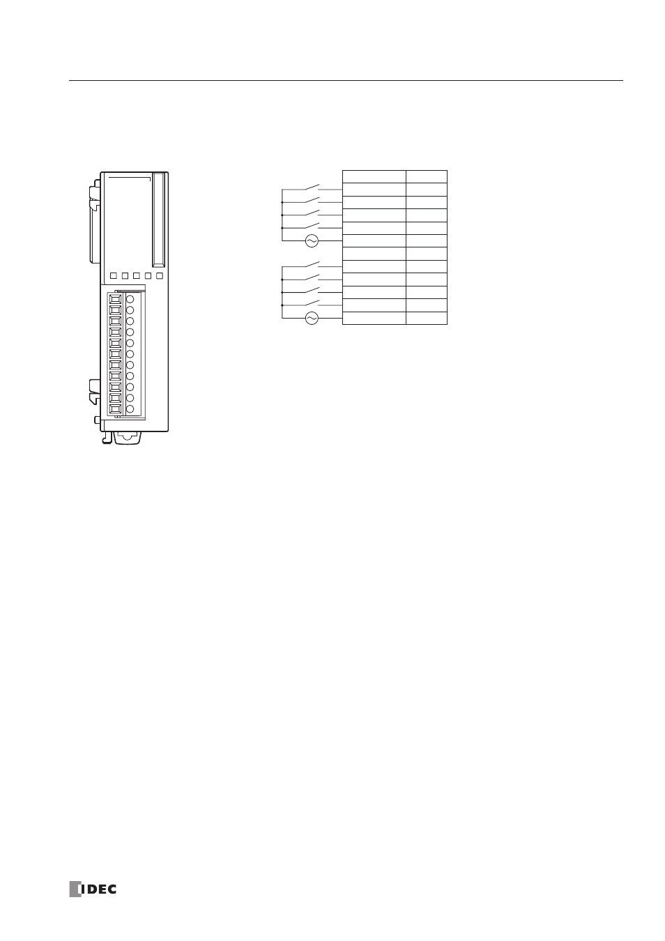
AC Input Module Terminal Arrangement and Wiring Diagrams
FC4A-N08A11 (8-point AC Input Module) — Screw Terminal Type
Applicable Terminal Block:
FC4A-PMT11P (supplied with the input module)
7
COM1
0
1
2
3
4
5
6
7
AC.IN
1
02
3
COM0
NC
4
5
6
Terminal No.
Output
0
I0
1
I1
2
I2
3
I3
COM0
COM0
NC
NC
4
I4
5
I5
6
I6
7
I7
COM1
COM1
AC
AC
• Two COM terminals are not connected together internally.
• For input wiring precautions, see page 3-13.
• Do not connect an external load to the input terminals.