IDEC MicroSmart User Manual
Page 61
2: M
ODULE
S
PECIFICATIONS
« FC4A M
ICRO
S
MART
U
SER
’
S
M
ANUAL
»
2-41
Relay Output Specifications (Mixed I/O Module)
Output Delay
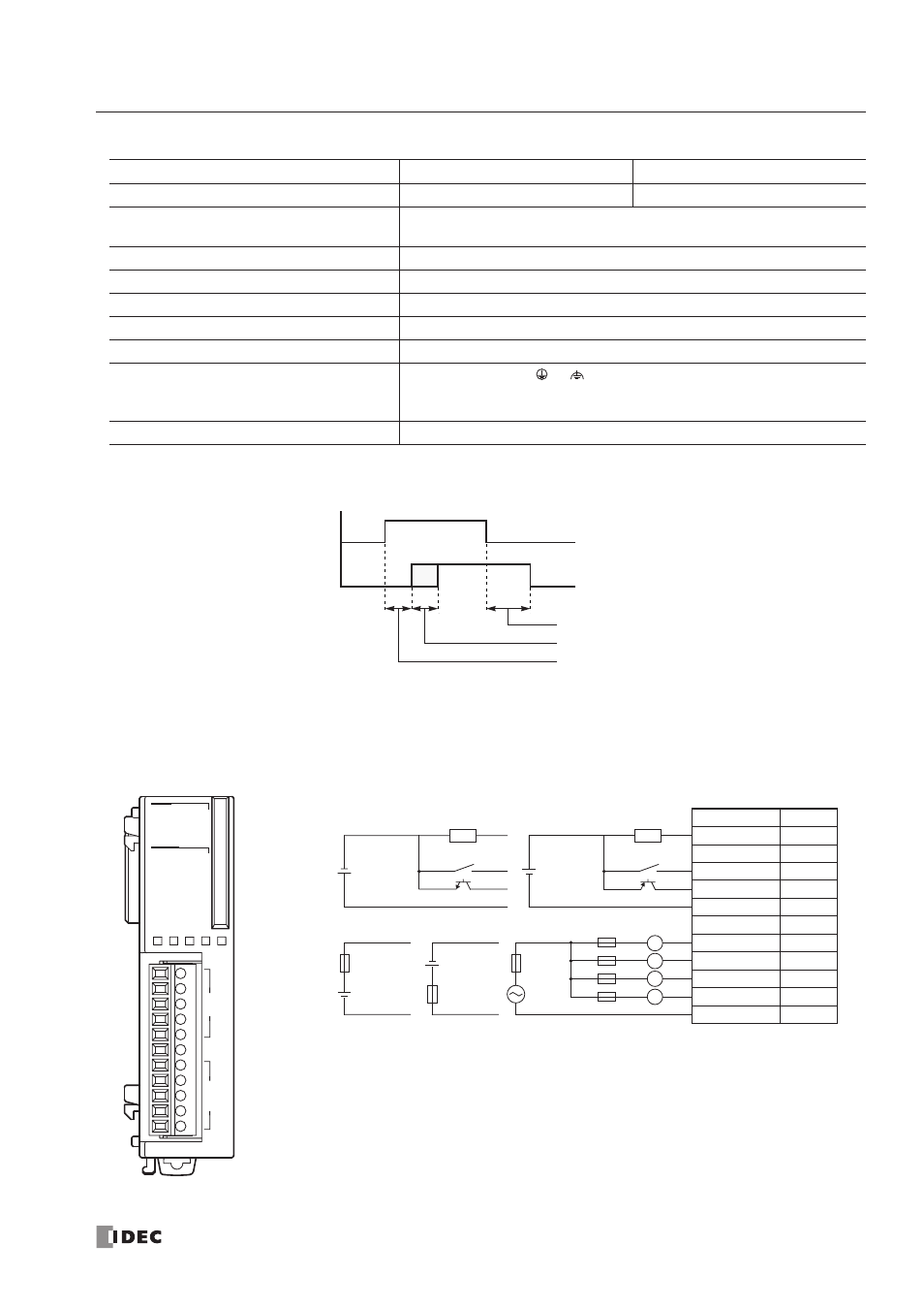
Mixed I/O Module Terminal Arrangement and Wiring Diagrams
FC4A-M08BR1 (Mixed I/O Module) — Screw Terminal Type
Applicable Terminal Block:
FC4A-PMT11P (supplied with the mixed I/O module)
Type No.
FC4A-M08BR1
FC4A-M24BR2
Output Points and Common Lines
4 NO contacts in 1 common line
8 NO contacts in 2 common lines
Maximum Load Current
2A per point
7A per common line
Minimum Switching Load
0.1 mA/0.1V DC (reference value)
Initial Contact Resistance
30 m
Ω maximum
Electrical Life
100,000 operations minimum (rated load 1,800 operations/hour)
Mechanical Life
20,000,000 operations minimum (no load 18,000 operations/hour)
Rated Load (resistive/inductive)
240V AC/2A, 30V DC/2A
Dielectric Strength
Between output and
or
terminals:
1,500V AC, 1 minute
Between output terminal and internal circuit: 1,500V AC, 1 minute
Between output terminals (COMs):
1,500V AC, 1 minute
Contact Protection Circuit for Relay Output
Command
Output Relay Status
OFF delay:
10 ms maximum
Chatter:
6 ms maximum
ON delay:
6 ms maximum
ON
OFF
ON
OFF
L
3
COM1
0
1
2
3
0
1
2
3
DC.IN
Ry.OUT
1
02
3
COM0
NC
012
Ry.OUT
DC.IN
Terminal No.
I/O
0
I0
1
I1
2
I2
3
I3
COM0
COM0
NC
NC
0
Q0
1
Q1
2
Q2
3
Q3
COM1
COM1
Fuse
L
AC
Fuse
Fuse
DC
DC
Load
L
L
+
–
+
–
+
–
Sink Input Wiring
• COM0 and COM1 terminals are not connected together internally.
• For wiring precautions, see pages 3-13 and 3-14.
Fuse
Relay Output Wiring
24V DC
+ –
2-wire Sensor
PNP
+
–
Source Input Wiring
24V DC
+
–
2-wire Sensor
NPN