IDEC MicroSmart User Manual
Page 27
2: M
ODULE
S
PECIFICATIONS
« FC4A M
ICRO
S
MART
U
SER
’
S
M
ANUAL
»
2-7
Relay Output Specifications (All-in-One Type CPU Module)
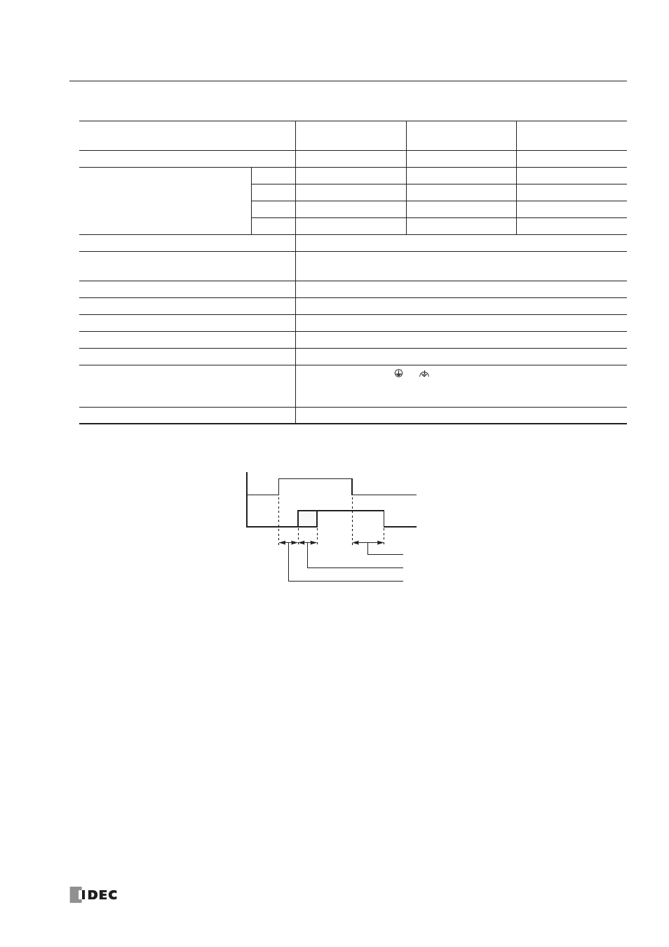
Output Delay
CPU Module
FC4A-C10R2
FC4A-C10R2C
FC4A-C16R2
FC4A-C16R2C
FC4A-C24R2
FC4A-C24R2C
No. of Outputs
4 points
7 points
10 points
Output Points per Common Line
COM0
3 NO contacts
4 NO contacts
4 NO contacts
COM1
1 NO contact
2 NO contacts
4 NO contacts
COM2
—
1 NO contact
1 NO contact
COM3
—
—
1 NO contact
Terminal Arrangement
See CPU Module Terminal Arrangement on pages 2-8 and 2-9.
Maximum Load Current
2A per point
8A per common line
Minimum Switching Load
0.1 mA/0.1V DC (reference value)
Initial Contact Resistance
30 m
Ω maximum
Electrical Life
100,000 operations minimum (rated load 1,800 operations/hour)
Mechanical Life
20,000,000 operations minimum (no load 18,000 operations/hour)
Rated Load (resistive/inductive)
240V AC/2A, 30V DC/2A
Dielectric Strength
Between output and
or
terminals:
1,500V AC, 1 minute
Between output terminal and internal circuit: 1,500V AC, 1 minute
Between output terminals (COMs):
1,500V AC, 1 minute
Contact Protection Circuit for Relay Output
Command
Output Relay Status
OFF delay:
10 ms maximum
Chatter:
6 ms maximum
ON delay:
6 ms maximum
ON
OFF
ON
OFF