IDEC MicroSmart User Manual
Page 169
6: A
LLOCATION
N
UMBERS
« FC4A M
ICRO
S
MART
U
SER
’
S
M
ANUAL
»
6-5
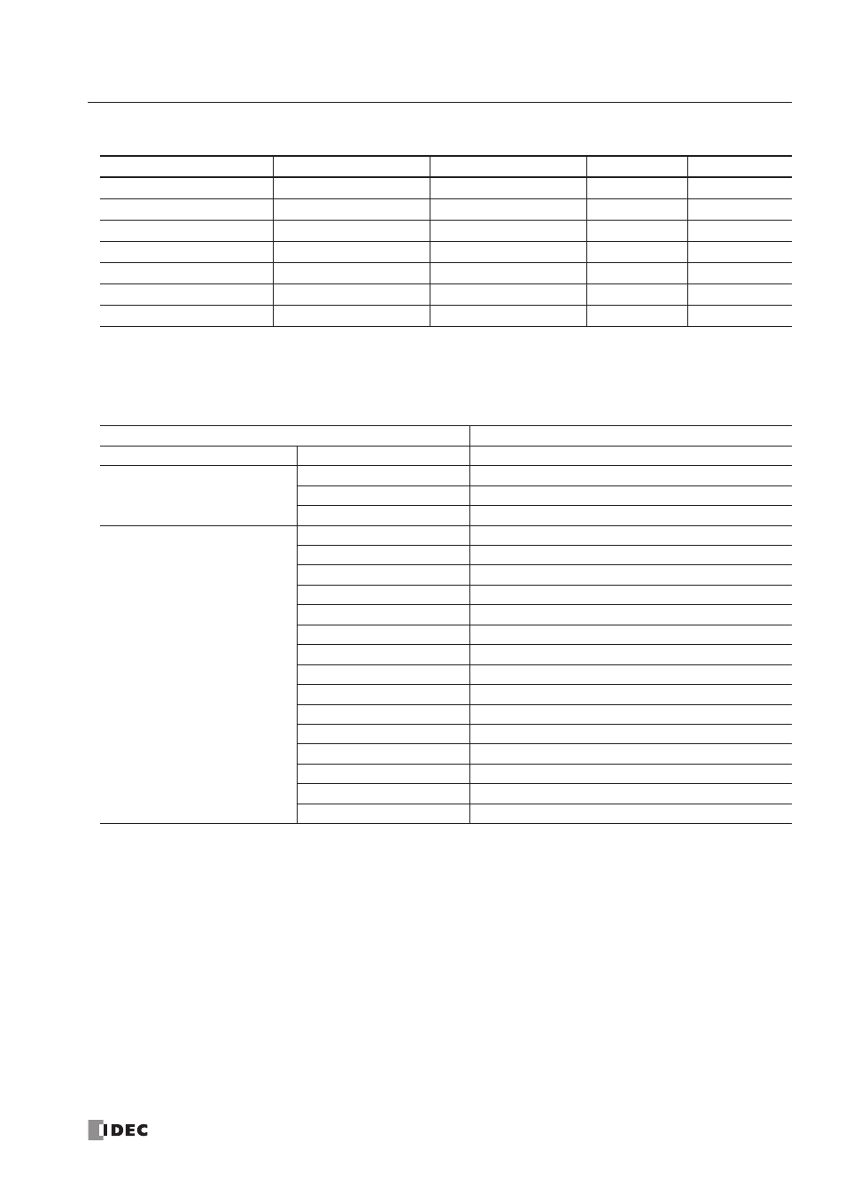
Operand Allocation Numbers for END Refresh Type Analog I/O Modules
Note: Each analog I/O module uses 20 data registers. When analog modules are not connected, the corresponding data
registers can be used as ordinar y data registers.
Operand Allocation Numbers for AS-Interface Master Module
Note: AS-Inter face master module uses internal relays and data registers shown above. When AS-Inter face master module
is not connected, these internal relays and data registers can be used as ordinar y internal relays and data registers.
Analog I/O Module Number
Analog Input Channel 0
Analog Input Channel 1
Analog Output
Reserved
1
D760-D765
D766-D771
D772-D777
D778, D779
2
D780-D785
D786-D791
D792-D797
D798, D799
3
D800-D805
D806-D811
D812-D817
D818, D819
4
D820-D825
D826-D831
D832-D837
D838, D839
5
D840-D845
D846-D851
D852-D857
D858, D859
6
D860-D865
D866-D871
D872-D877
D878, D879
7
D880-D885
D886-D891
D892-D897
D898, D899
MicroSmart CPU Module
AS-Interface Master Module EEPROM
Operand
Allocation No.
AS-Interface Object
AS-Interface Internal Relays
M1300-M1617
Digital input (IDI)
M1620-M1937
Digital output (ODI)
M1940-M1997
Status information
AS-Interface Data Registers
D1700-D1731
Analog input
D1732-D1763
Analog output
D1764-D1767
List of active slaves (LAS)
D1768-D1771
List of detected slaves (LDS)
D1772-D1775
List of peripheral fault slaves (LPF)
D1776-D1779
List of projected slaves (LPS)
D1780-D1811
Configuration data image A (CDI)
D1812-D1843
Configuration data image B (CDI)
D1844-D1875
Permanent configuration data A (PCD)
D1876-D1907
Permanent configuration data B (PCD)
D1908-D1923
Parameter image (PI)
D1924-D1939
Permanent parameter (PP)
D1940
Slave 0 ID1 code
D1941-D1945
For ASI command description
D1946-D1999
— Reser ved —