IDEC MicroSmart User Manual
Page 203
7: B
ASIC
I
NSTRUCTIONS
« FC4A M
ICRO
S
MART
U
SER
’
S
M
ANUAL
»
7-19
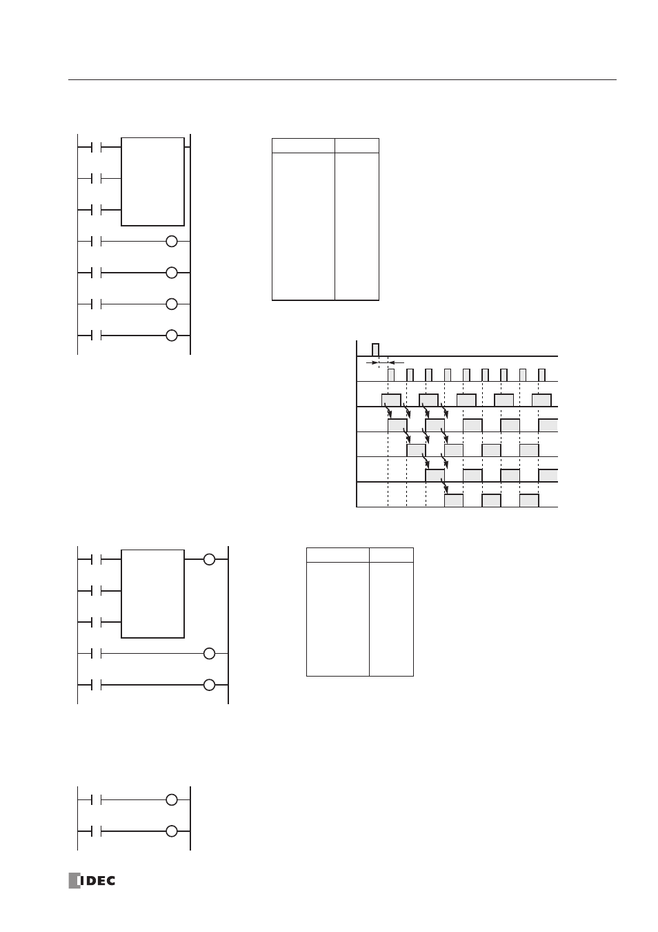
Forward Shift Register (SFR), continued
Setting and Resetting Shift Register Bits
Reset Input I0
ON
OFF
Pulse Input I1
ON
OFF
Data Input I2
ON
OFF
Timing Chart
R1/Q1
ON
OFF
One scan or more is required
R0/Q0
ON
OFF
R3/Q3
ON
OFF
R2/Q2
ON
OFF
Ladder Diagram
I0
I1
SFR
R0
4
I2
Reset
Pulse
Data
R0
R1
R2
R3
Instruction
Data
LOD
LOD
LOD
SFR
LOD
OUT
LOD
OUT
LOD
OUT
LOD
OUT
I0
I1
I2
R0
4
R0
Q0
R1
Q1
R2
Q2
R3
Q3
Program List
Q0
Q1
Q2
Q3
• The last bit status output can be programmed directly after
the SFR instruction. In this example, the status of bit R3 is
read to output Q3.
• Each bit can be loaded using the LOD R# instruction.
Instruction
Data
LOD
LOD
LOD
SFR
OUT
LOD
OUT
LOD
OUT
I1
I2
I3
R0
4
Q3
R0
Q0
R1
Q1
Program List
Ladder Diagram
I1
I2
SFR
R0
4
I3
Reset
Pulse
Data
R0
R1
Q0
Q1
Q3
I1
I0
• Any shift register bit can be turned on using the SET instruction.
• Any shift register bit can be turned off using the RST instruction.
• The SET or RST instruction is actuated by any input condition.
R0
S
R3
R