IDEC MicroSmart User Manual
Page 296
17: U
SER
C
OMMUNICATION
I
NSTRUCTIONS
17-18
« FC4A M
ICRO
S
MART
U
SER
’
S
M
ANUAL
»
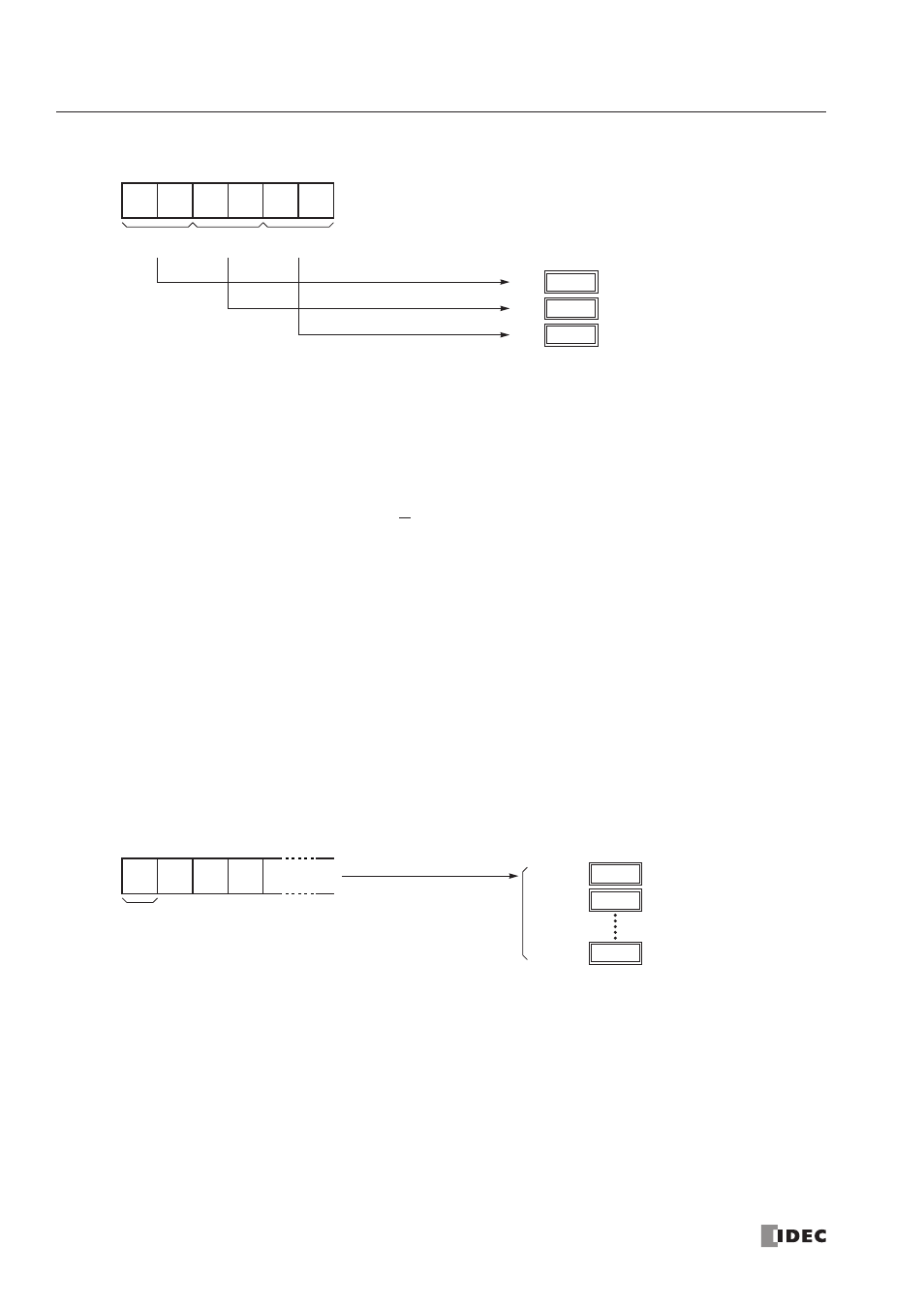
(2) Repeat cycles = 3
Designating Constant as Start Delimiter
A start delimiter can be programmed at the first byte in the receive format of a RXD1/RXD2 instruction; the
MicroSmart
will recognize the beginning of valid communication, although a RXD1/RXD2 instruction without a start delimiter can
also be executed.
When a constant value is designated at the first byte of source operand S1, the one-byte data serves as a start delimiter to
start the processing of the received data. The valid start delimiter value depends on the data bits selected in the Communi-
cation Parameters dialog box, which is called from Configure > Fun Area Settings > Communication, followed by
selecting User Protocol in Port 1 or Port 2 list box and clicking the Configure button. When 7 data bits are selected as
default, start delimiters can be 00h through 7Fh. When 8 data bits are selected, start delimiters can be 00h through FFh.
Constant values are entered in character or hexadecimal notation into the source data.
A maximum of five RXD1 and five RXD2 instructions with different start delimiters can be executed at the same time.
When the first byte of the incoming data matches the start delimiter of a RXD1/RXD2 instruction, the received data is pro-
cessed and stored according to the receive format specified in the RXD1/RXD2 instruction. If the first byte of the incom-
ing data does not match the start delimiter of any RXD1/RXD2 instruction that is executed, the
MicroSmart
discards the
incoming data and waits for the next communication.
While a RXD1/RXD2 instruction without a start delimiter is executed, any incoming data is processed continuously
according to the receive format. Only one RXD1 and one RXD2 instructions without a start delimiter can be executed at a
time. If start inputs to two or more RXD1/RXD2 instructions without a start delimiter are turned on simultaneously, one at
the smallest address is executed and the corresponding completion output is turned on.
Example:
(1) When a RXD1/RXD2 instruction without a start delimiter is executed
0012h
D20
Repeat 1
0034h
D21
ASCII to Binar y conversion
Repeat 2
“1”
(31h)
“2”
(32h)
2 digits
1st block
“3”
(33h)
“4”
(34h)
2 digits
2nd block
“5”
(35h)
“6”
(36h)
2 digits
3rd block
0056h
D22
Repeat 3
****h
D100
When D100 is designated as the first data register
“0”
(30h)
“1”
(31h)
1st
character
“2”
(32h)
“3”
(33h)
Incoming Data
****h
D100+n
****h
D101
The incoming data is divided, converted, and stored to data registers according to the receive format.