IDEC MicroSmart User Manual
Page 104
3: I
NSTALLATION
AND
W
IRING
3-10
« FC4A M
ICRO
S
MART
U
SER
’
S
M
ANUAL
»
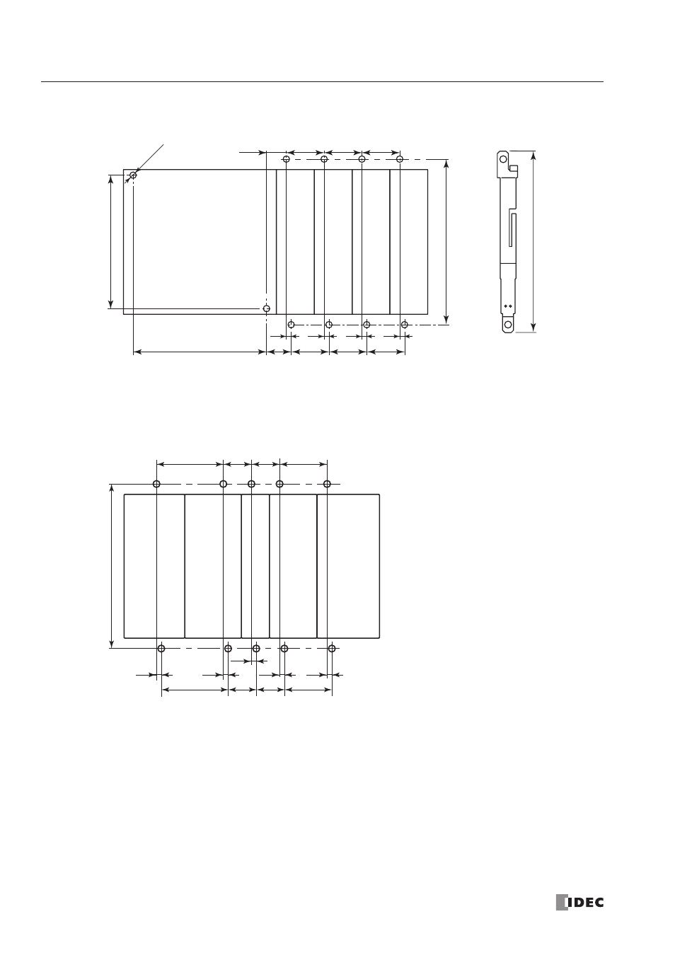
Example 1: Mounting hole layout for FC4A-C24R2 and 23.5-mm-wide I/O modules
Example 2: Mounting hole layout for, from left, FC4A-HPH1, FC4A-D20K3, FC4A-N16B3, FC4A-N32B3, and
FC4A-M24R2 modules
3.0
3.0
3.0
3.0
23.5
83.0
83.0
10-ø4.3
103.0
113.0
±
0.2
15.3
23.5
23.5
12.3
23.5
23.5
23.5
Direct Mounting Strip
FC4A-PSP1P
41.8
17.6
17.6
29.7
41.8
17.6
17.6
29.7
3.0
3.0
3.0
3.0
103.0
3.0
All dimensions in mm.