IDEC MicroSmart User Manual
Page 65
2: M
ODULE
S
PECIFICATIONS
« FC4A M
ICRO
S
MART
U
SER
’
S
M
ANUAL
»
2-45
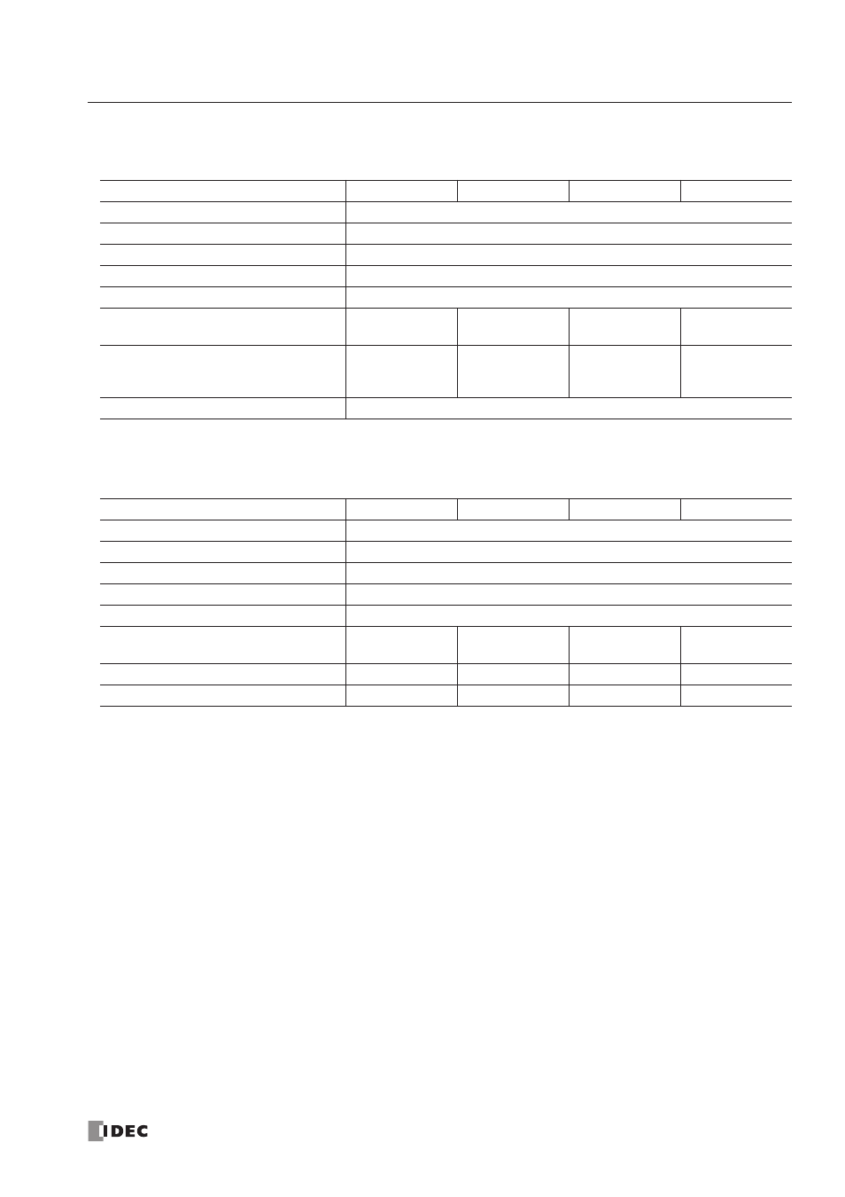
Analog I/O Module Specifications
General Specifications (END Refresh Type)
Note 1: The external current draw is the value when all analog inputs are used and the analog output value is at 100%.
Note 2: Values in ( ) represent analog I/O modules earlier than version 200. For analog I/O module version, see page 2-44.
General Specifications (Ladder Refresh Type)
Note: The external current draw is the value when all analog inputs are used and the analog output value is at 100%.
Type No.
FC4A-L03A1
FC4A-L03AP1
FC4A-J2A1
FC4A-K1A1
Rated Power Voltage
24V DC
Allowable Voltage Range
20.4 to 28.8V DC
Terminal Arrangement
See Analog I/O Module Terminal Arrangement on pages 2-52 to 2-55.
Connector on Mother Board
MC1.5/11-G-3.81BK (Phoenix Contact)
Connector Insertion/Removal Durability
100 times minimum
Internal Current Draw
50 mA (5V DC)
0 mA (24V DC)
50 mA (5V DC)
0 mA (24V DC)
50 mA (5V DC)
0 mA (24V DC)
50 mA (5V DC)
0 mA (24V DC)
External Current Draw (Note 1)
50 (45) mA
(Note 2)
(24V DC)
50 (40) mA
(Note 2)
(24V DC)
40 (35) mA
(Note 2)
(24V DC)
40 mA (24V DC)
Weight (Approx.)
100g (85g) (Note 2)
Type No.
FC4A-J4CN1
FC4A-J8C1
FC4A-J8AT1
FC4A-K2C1
Rated Power Voltage
24V DC
Allowable Voltage Range
20.4 to 28.8V DC
Terminal Arrangement
See Analog I/O Module Terminal Arrangement on pages 2-52 to 2-55.
Connector on Mother Board
MC1.5/10-G-3.81BK (Phoenix Contact)
Connector Insertion/Removal Durability
100 times minimum
Internal Current Draw
50 mA (5V DC)
0 mA (24V DC)
40 mA (5V DC)
0 mA (24V DC)
45 mA (5V DC)
0 mA (24V DC)
60 mA (5V DC)
0 mA (24V DC)
External Current Draw (Note)
55 mA (24V DC)
50 mA (24V DC)
55 mA (24V DC)
85 mA (24V DC)
Weight
140g
140g
125g
110g