As-interface master module – IDEC MicroSmart User Manual
Page 78
2: M
ODULE
S
PECIFICATIONS
2-58
« FC4A M
ICRO
S
MART
U
SER
’
S
M
ANUAL
»
AS-Interface Master Module
The AS-Interface master module can be used with FC4A-D20RK1, FC4A-D20RS1, FC4A-D40K3, and FC4A-D40S3
CPU modules to communicate digital data with slaves, such as sensor, actuator, and remote I/O data.
One AS-Interface master module can be used with one CPU module. The AS-Interface master module can connect a max-
imum of 62 digital I/O slaves. A maximum of seven analog I/O slaves can also be connected to the AS-Interface master
module (compliant with AS-Interface ver. 2.1 and analog slave profile 7.3).
AS-Interface Master Module Type Number
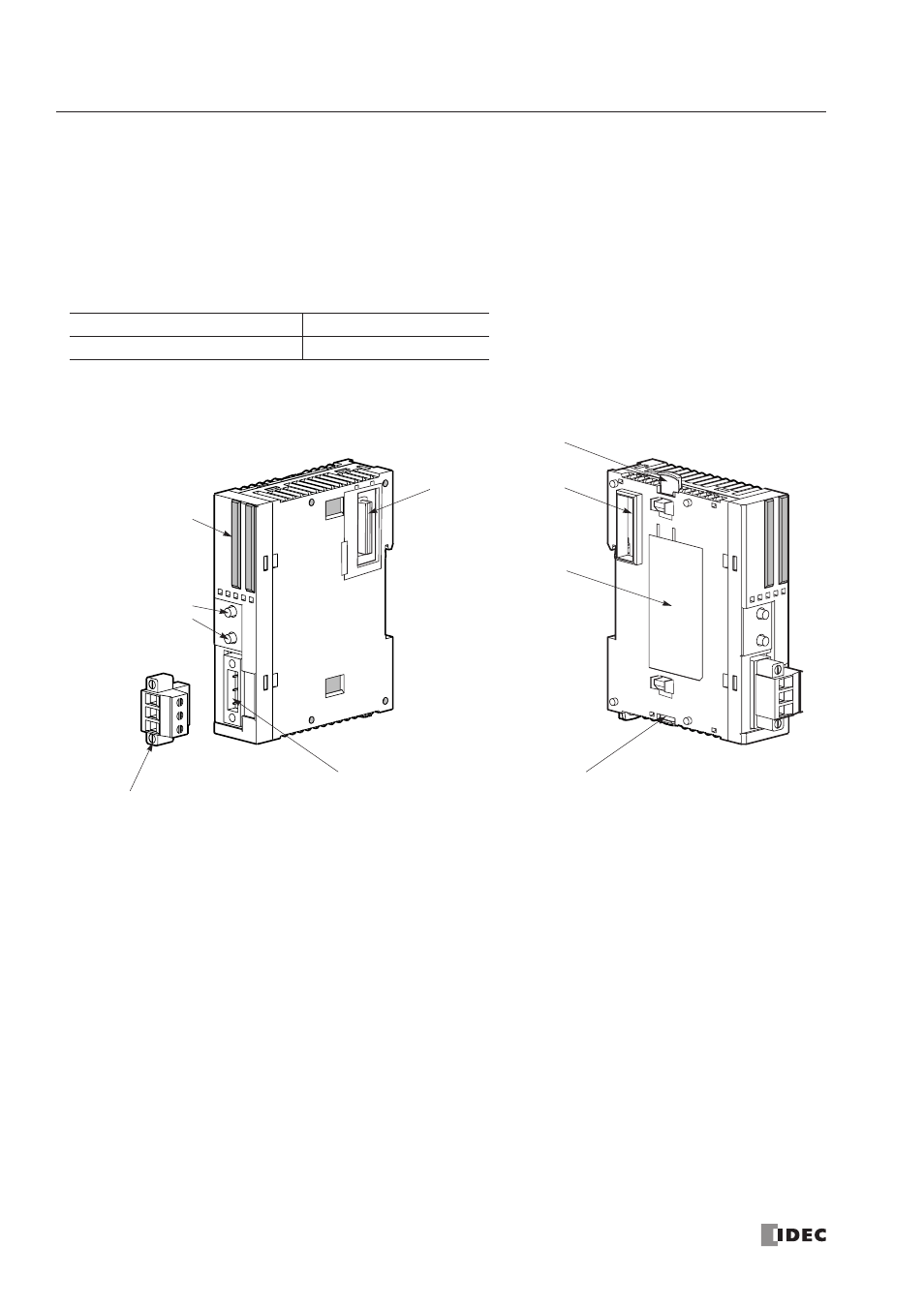
Parts Description
(1) LED Indicators
Status LEDs:
Indicate the AS-Interface bus status.
I/O LEDs:
Indicate the I/O status of the slave specified by the address LEDs.
Address LEDs:
Indicate slave addresses.
(2) Pushbuttons
Used to select slave addresses, change modes, and store configuration.
(3) AS-Interface Cable Terminal Block
Connects the AS-Interface cable.
One terminal block is supplied with the AS-Interface master module.
When ordering separately, specify Type No. FC4A-PMT3P and quantity
(package quantity: 2).
(4) AS-Interface Cable Connector
Installs the AS-Interface cable terminal block.
(5) Unlatch Button
Used to unlatch the AS-Interface master module from the CPU or I/O module.
(6) Expansion Connector
Connects to the CPU and other I/O modules.
(7) Module Label
Indicates the AS-Interface master module Type No. and specifications.
Module Name
Type No.
AS-Interface Master Module
FC4A-AS62M
(6) Expansion Connector
(7) Module Label
(1) LED Indicators
(4) AS-Inter face Cable Connector
(2) Pushbuttons
PB1
PB2
(5) Unlatch Button
(5) Unlatch Button
(3) AS-Inter face Cable Terminal Block
(supplied with the AS-Inter face master module)