User communication mode specifications – IDEC MicroSmart User Manual
Page 280
17: U
SER
C
OMMUNICATION
I
NSTRUCTIONS
17-2
« FC4A M
ICRO
S
MART
U
SER
’
S
M
ANUAL
»
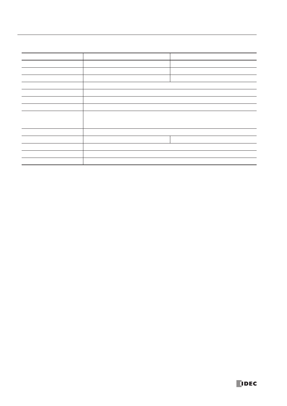
User Communication Mode Specifications
Note *: WindLDR 4.0 or higher is needed to use these BCC calculation formulas.
Connecting RS232C Equipment through RS232C Port 1 or 2
When using port 2 for RS232C communication on the all-in-one 16- or 24-I/O type CPU module, install the RS232C com-
munication adapter (FC4A-PC1) to the port 2 connector.
When using port 2 for RS232C communication on the slim type CPU module, mount the RS232C communication module
(FC4A-HPC1) next to the CPU module.
When using port 2 for RS232C communication on the slim type CPU module with the optional HMI module, install the
RS232C communication adapter (FC4A-PC1) to the port 2 connector on the HMI base module.
To connect an RS232C communication device to the RS232C port 1 or 2 on the
MicroSmart
CPU module, use the user
communication cable 1C (FC2A-KP1C). One end of the user communication cable 1C is not provided with a connector,
and can be terminated with a proper connector to plug in to communicate with the RS232C port. See the figure on
page 17-3.
Type
RS232C User Communication
RS485 User Communication
Communication Port
Por t 1 and Por t 2
Por t 2
Connection Device Quantity
1 per por t
31 maximum
Standards
EIA RS232C
EIA RS485
Baud Rate
1200, 2400, 4800, 9600, 19200 bps
Data Bits
7 or 8 bits
Parity
Odd, Even, None
Stop Bits
1 or 2 bits
Receive Timeout
10 to 2540 msec (10-msec increments) or none
(Receive timeout is disabled when 2550 msec is selected.)
The receive timeout has an effect when using RXD1/RXD2 instructions.
Communication Method
Star t-stop synchronization system half-duplex
Maximum Cable Length
2.4m
200m
Maximum Transmit Data
200 bytes
Maximum Receive Data
200 bytes
BCC Calculation
XOR, ADD, ADD-2comp *, Modbus ASCII *, Modbus RTU *