IDEC MicroSmart User Manual
Page 326
19: C
OORDINATE
C
ONVERSION
I
NSTRUCTIONS
19-4
« FC4A M
ICRO
S
MART
U
SER
’
S
M
ANUAL
»
Valid Operands
For the valid operand number range, see pages 6-1 and 6-2.
▲
Internal relays M0 through M1277 can be designated as D1. Special internal relays cannot be designated as D1.
When T (timer) or C (counter) is used as S2, the timer/counter current value is read out. When T (timer) or C (counter) is
used as D1, the data is written in as a preset value which can be 0 through 65535.
S1 (Format number)
Select a format number 0 through 5 which have been set using the XYFS instruction. When an XYFS instruction with
the corresponding format number is not programmed, or when XYFS and CVYTX instructions of the same format
number have different data type designations, a user program execution error will result, turning on special internal
relay M8004 and the ERR LED.
S2 (Y value)
Enter a value for the Y coordinate to convert, within the range specified in the XYFS instruction. Any value out of the
range specified in the XYFS results in a user program execution error, turning on special internal relay M8004 and the
ERR LED. Three different data ranges are available depending on the system program version and the data type.
D1 (Destination to store results)
The conversion result of the X value is stored to the destination. The data range depends on the available data type.
Valid Data Types
Data Conversion Error
The data conversion error is ±0.5.
Operand
Function
I
Q
M
R
T
C
D
Constant
Repeat
S1 (Source 1)
Format number
—
—
—
—
—
—
—
0 to 5
—
S2 (Source 2)
Y value
X
X
X
X
X
X
X
0 to 65535
–32768 to 32767
—
D1 (Destination 1)
Destination to store results
—
X
▲ X
X
X
X
—
—
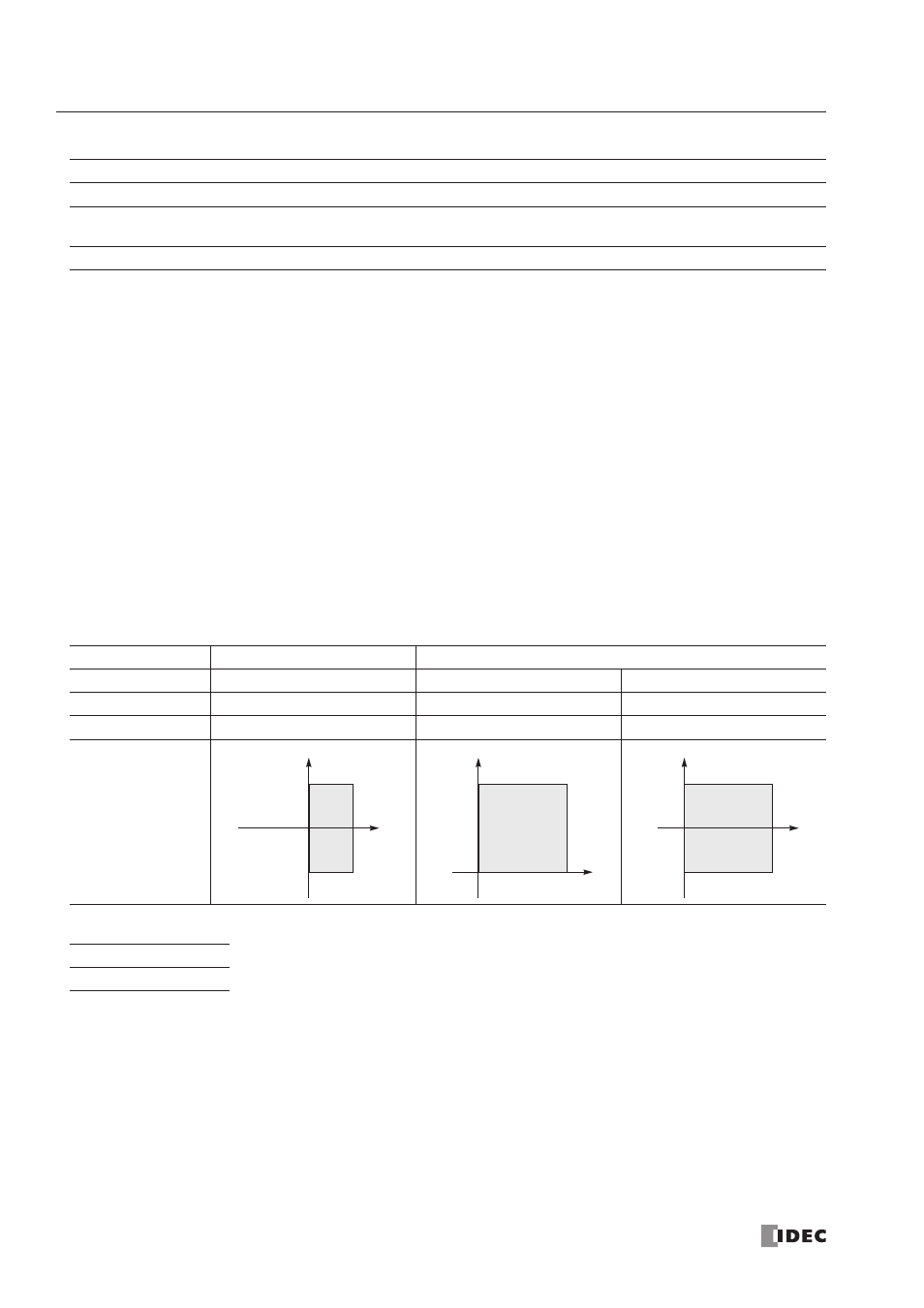
System Program
Old System Program Versions
Upgraded System Program Versions
Data Type
Integer
Word
Integer
S2 (Y value)
–32768 to 32767
0 to 65535
–32768 to 32767
D1 (X value)
0 to 32767
0 to 65535
0 to 65535
Valid Coordinates
W (word)
I (integer)
X
X
Y
0
32767
–32768
X
32767
Y
0
65535
65535
X
Y
0
32767
–32768
X
65535
When a bit operand such as I (input), Q (output), M (internal relay), or R (shift register) is
designated as S2 or D1, 16 points are used.
When a word operand such as T (timer), C (counter), or D (data register) is designated as S2
or D1, 1 point (integer data type) is used.