Assembling modules, Disassembling modules – IDEC MicroSmart User Manual
Page 96
3: I
NSTALLATION
AND
W
IRING
3-2
« FC4A M
ICRO
S
MART
U
SER
’
S
M
ANUAL
»
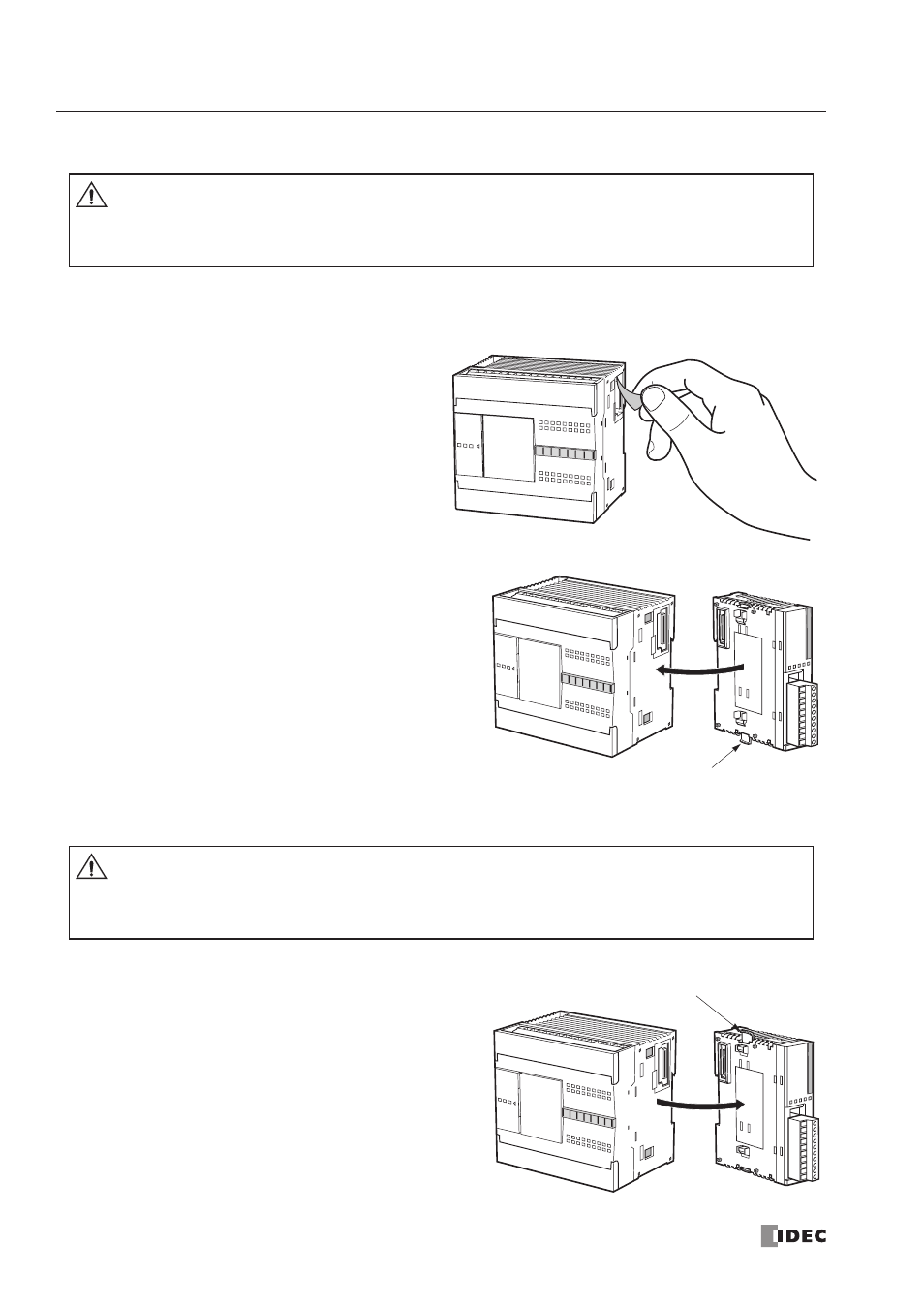
Assembling Modules
The following example demonstrates the procedure for assembling the all-in-one 24-I/O type CPU module and an I/O
module together. When assembling slim type CPU modules, take the same procedure.
1. When assembling an input or output module,
remove the expansion connector seal from the
24-I/O type CPU module.
2. Place the CPU module and I/O module side by side. Put the
expansion connectors together for easy alignment.
3. With the expansion connectors aligned correctly and the
blue unlatch button in the down position, press the CPU
module and I/O module together until the latches click to
attach the modules together firmly. If the unlatch button is
in the up position, push down the button to engage the
latches.
Disassembling Modules
1. If the modules are mounted on a DIN rail, first remove the
modules from the DIN rail as described on page 3-7.
2. Push up the blue unlatch button to disengage the latches,
and pull the modules apart as shown. When disassembling
slim type CPU modules, take the same procedure.
Caution
• Assemble
MicroSmart
modules together before mounting the modules onto a DIN rail. Attempt
to assemble modules on a DIN rail may cause damage to the modules.
• Turn off the power to the
MicroSmart
before assembling the modules. Failure to turn power off
may cause electrical shocks.
Unlatch Button
Caution
• Remove the
MicroSmart
modules from the DIN rail before disassembling the modules. Attempt
to disassemble modules on a DIN rail may cause damage to the modules.
• Turn off the power to the
MicroSmart
before disassembling the modules. Failure to turn power
off may cause electrical shocks.
Unlatch Button