Removing the communication connector cover – IDEC MicroSmart User Manual
Page 100
3: I
NSTALLATION
AND
W
IRING
3-6
« FC4A M
ICRO
S
MART
U
SER
’
S
M
ANUAL
»
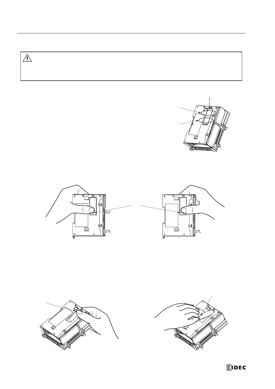
Removing the Communication Connector Cover
Before mounting a communication module or HMI base module next
to the slim type CPU module, the communication connector cover
must be removed from the CPU module. Break the communication
connector cover on the slim type CPU module as described below.
1. Carefully push in the communication connector cover at position (1) to break bridges A as shown in either figure
below.
2. The other end (2) of the communication connector cover will come out as shown at left below. Push in this end.
3. Then, the opposite end (3) will come out. If the end does not come out, insert a thin screwdriver into the gap and pull
out the end (3).
Hold the communication connector cover at (3), and pull off the communication connector cover to break bridges B.
Caution
• When using a thin screwdriver to pull out the communication connector cover, insert the screw-
driver carefully and do not damage the electronic parts inside the CPU module.
• When first pushing in the communication connector cover to break, take care not to injure your
finger.
Bridges B
Bridges A
Communication
Connector Cover
(1)
(2)
(3)