IDEC MicroSmart User Manual
Page 131
5: S
PECIAL
F
UNCTIONS
« FC4A M
ICRO
S
MART
U
SER
’
S
M
ANUAL
»
5-11
Programming WindLDR (All-in-One Type CPU Modules)
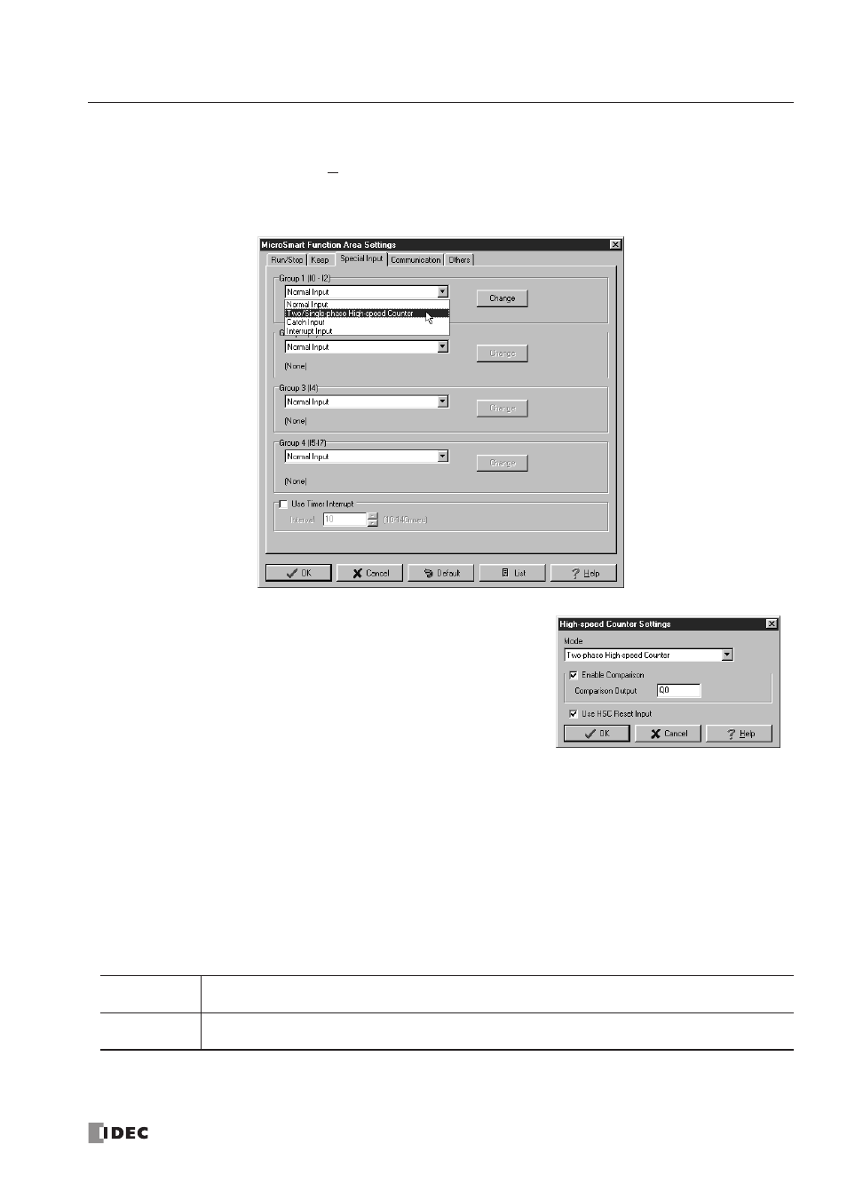
1. From the
WindLDR
menu bar, select Configure > Function Area Settings. The Function Area Settings dialog box
appears.
2. Select the Special Input tab.
3. When using high-speed counter HSC1, select Two/Single-phase
High-speed Counter in the Group 1 pull-down list box.
When using high-speed counters HSC2 through HSC4, select
Single-phase High-speed Counter in the Groups 2 through 4
pull-down list boxes.
The High-speed Counter Settings dialog box appears.
Mode
Select Two-phase High-speed Counter or Single-phase High-speed Counter for HSC1. Only Single-phase High-speed
Counter is available for HSC2 through HSC4.
Enable Comparison
Click the check box to enable the high-speed counter comparison output, and specify an output number available on the
CPU module in the Comparison Output field. When current value overflow or underflow occurs (two-phase high-speed
counter) or when the preset value is reached (single-phase high-speed counter), the specified comparison output is turned
on and remains on until a comparison output reset special internal relay (M8030, M8034, M8040, or M8044) is turned on.
Use HSC Reset Input
Click the check box to enable high-speed counter reset input I2 for HSC1 only. When input I2 is turned on, the current
value in D8045 is reset depending on the high-speed counter mode.
Since these settings relate to the user program, the user program must be downloaded to the
MicroSmart
after changing
any of these settings.
Two-phase
The current value is reset to the value stored in D8046 (high-speed counter reset value). The two-phase
high-speed counter counts subsequent input pulses star ting at the reset value.
Single-phase
The current value is reset to 0. The value stored in D8046 (high-speed counter preset value) at this
point takes effect for the subsequent counting cycle.