Ibmvn (indirect bit move not) – IDEC MicroSmart User Manual
Page 228
9: M
OVE
I
NSTRUCTIONS
9-10
« FC4A M
ICRO
S
MART
U
SER
’
S
M
ANUAL
»
IBMVN (Indirect Bit Move Not)
Applicable CPU Modules
Valid Operands
For the valid operand number range, see pages 6-1 and 6-2.
▲
Internal relays M0 through M1277 can be designated as D1. Special internal relays cannot be designated as D1.
When T (timer) or C (counter) is used as S2 or D2, the timer/counter current value is read out.
Make sure that the last source data determined by S1+S2 and the last destination data determined by D1+D2 are within the
valid operand range. If the derived source or destination operand is out of the valid operand range, a user program execu-
tion error will result, turning on special internal relay M8004 and ERR LED on the CPU module.
Either source operand S2 or destination operand D2 does not have to be designated. If S2 or D2 is not designated, the
source or destination operand is determined by S1 or D1 without offset.
Examples: IBMVN
Source operand S1 and destination operand D1 determine the type of operand. Source operand S2 and destination operand
D2 are the offset values to determine the source and destination operands.
As a result, when input I0 is on, the ON/OFF status of internal relay M30 is inver ted and moved to output Q22.
FC4A-C10R2/C
FC4A-C16R2/C
FC4A-C24R2/C
FC4A-D20K3/S3
FC4A-D20RK1/RS1 & FC4A-D40K3/S3
—
—
—
—
X
Operand
Function
I
Q
M
R
T
C
D
Constant
Repeat
S1 (Source 1)
Base address to move from
X
X
X
X
—
—
X
0 or 1
1-99
S2 (Source 2)
Offset for S1
X
X
X
X
X
X
X
0-65535
—
D1 (Destination 1)
Base address to move to
—
X
▲ X — — X
—
1-99
D2 (Destination 2)
Offset for D1
X
X
X
X
X
X
X
0-65535
—
S1 + S2 NOT
→ D1 + D2
When input is on, the values contained in operands des-
ignated by S1 and S2 are added to determine the source
of data. The 1-bit data so determined is inver ted and
moved to destination, which is determined by the sum of
values contained in operands designated by D1 and D2.
IBMVN
S1(R)
*****
S2
*****
D1(R)
*****
REP
**
D2
*****
S1 –
M20
I0
IBMVN
S2
D10
SOTU
D1 –
Q10
REP
D2
C5
M20
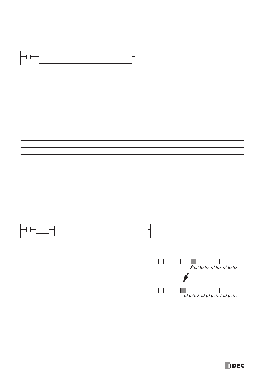
+ D10 NOT → Q10 + C5
M37
M20
M27
M30
8th from M20
Q27
Q10
Q17
Q20
10th from Q10
Q22
If the value of data register D10 designated by source operand
S2 is 8, the source data is determined by adding the offset to
internal relay M20 designated by source operand S1.
If the current value of counter C5 designated by destination oper-
and D2 is 10, the destination is determined by adding the offset
to output Q10 designated by destination operand D1.
NOT