IDEC MicroSmart User Manual
Page 94
2: M
ODULE
S
PECIFICATIONS
2-74
« FC4A M
ICRO
S
MART
U
SER
’
S
M
ANUAL
»
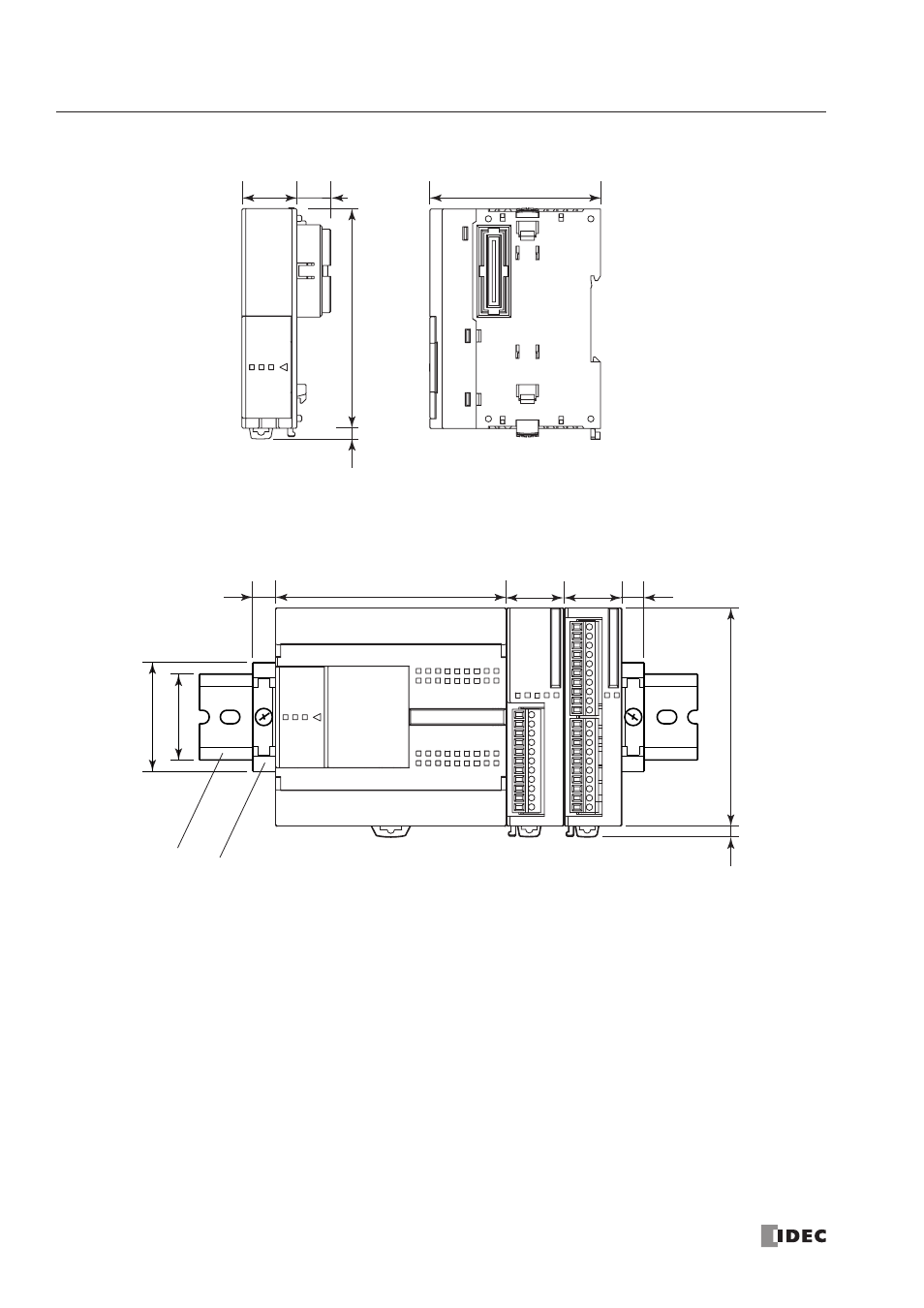
Communication Modules FC4A-HPC1, FC4A-HPC2, FC4A-HPC3
Example: The following figure illustrates a system setup consisting of the all-in-one 24-I/O type CPU module, an 8-point
relay output module, and a 16-point DC input module mounted on a 35-mm-wide DIN rail using BNL6P mounting clips.
22.5
13.9
70.0
90.0
4.5*
*8.5 mm when the clamp is pulled out.
All dimensions in mm.
*8.5 mm when the clamp is pulled out.
95.0
9.0
35.0
45.0
23.5
23.5
9.0
4.5*
90.0
BNL6P Mounting Clip
DIN Rail