IDEC MicroSmart User Manual
Page 356
20: P
ULSE
I
NSTRUCTIONS
20-28
« FC4A M
ICRO
S
MART
U
SER
’
S
M
ANUAL
»
Sample Program: ZRN1
This program demonstrates a user program of the ZRN1 instruction used for zero-return operation to generate output
pulses of 3 kHz initial pulse frequency from output Q0 while input I1 is on. When deceleration input I3 is turned on, the
output pulse frequency reduces to the creep pulse frequency of 800 Hz. When deceleration input I3 is turned off, ZRN1
stops generating output pulses.
Initial pulse frequency:
3,000 Hz
Creep pulse frequency:
800 Hz
Deceleration input:
I3 (high-speed deceleration input)
Operand Settings
Operand
Function
Description
Allocation No. (Value)
S1+0
Initial operation mode
Frequency range 100 to 10,000 Hz
D0 (1)
S1+1
Initial pulse frequency
10,000 Hz
× 30% = 3,000 Hz
D1 (30)
S1+2
Creep operation mode
Frequency range 10 to 1,000 Hz
D2 (0)
S1+3
Creep pulse frequency
1,000 Hz
× 80% = 800 Hz
D3 (80)
S1+4
Error status
D4
S2
Deceleration input
High-speed deceleration input
I3
D1+0
Pulse output ON
0: Pulse output OFF
1: Pulse output ON
M100
D1+1
Pulse output complete
0: Pulse output not complete
1: Pulse output complete
M101
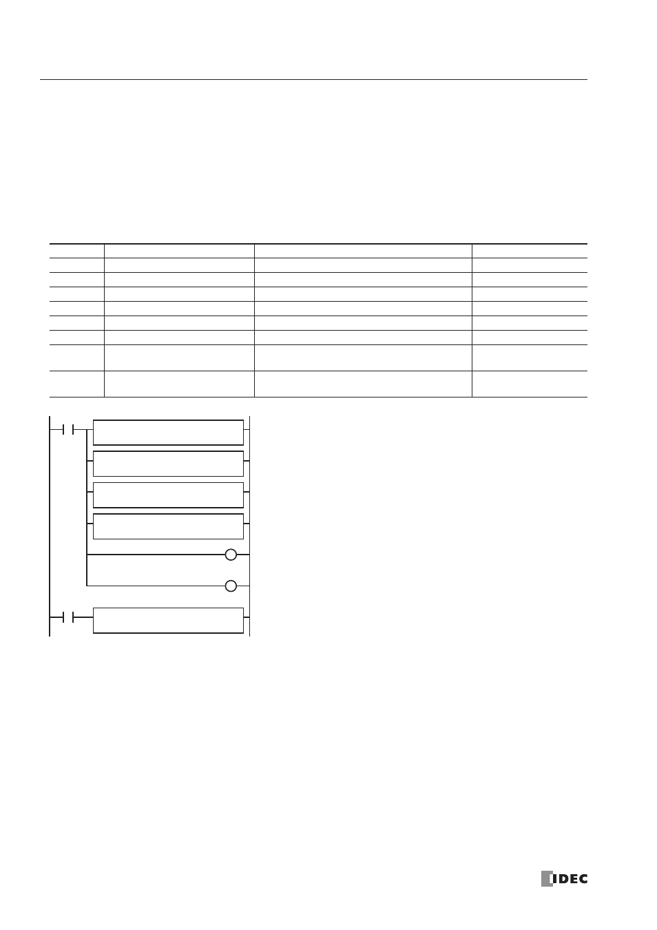
M8120
M8120 is the initialize pulse special internal relay.
When the CPU star ts, four MOV(W) instructions store parameters to data
registers D0 through D3.
D0 (initial operation mode): 1 (100 to 10,000 Hz)
D1 (initial pulse frequency): 30 (10,000 Hz
× 30% = 3,000 Hz)
D2 (creep operation mode): 0 (10 to 1,000 Hz)
D3 (creep pulse frequency): 80 (1,000 Hz
× 80% = 800 Hz)
Pulse output ON flag M100 is turned off.
Pulse output complete flag M101 is turned off.
When star t input I1 is turned on, ZRN1 star ts to generate output pulses
from output Q0.
I1
REP
S1 –
1
MOV(W)
D1 –
D0
REP
S1 –
30
MOV(W)
D1 –
D1
REP
S1 –
0
MOV(W)
D1 –
D2
REP
S1 –
80
MOV(W)
D1 –
D3
D1
M100
ZRN
1
S1
D0
M100
R
M101
R
S2
I3