IDEC MicroSmart User Manual
Page 71
2: M
ODULE
S
PECIFICATIONS
« FC4A M
ICRO
S
MART
U
SER
’
S
M
ANUAL
»
2-51
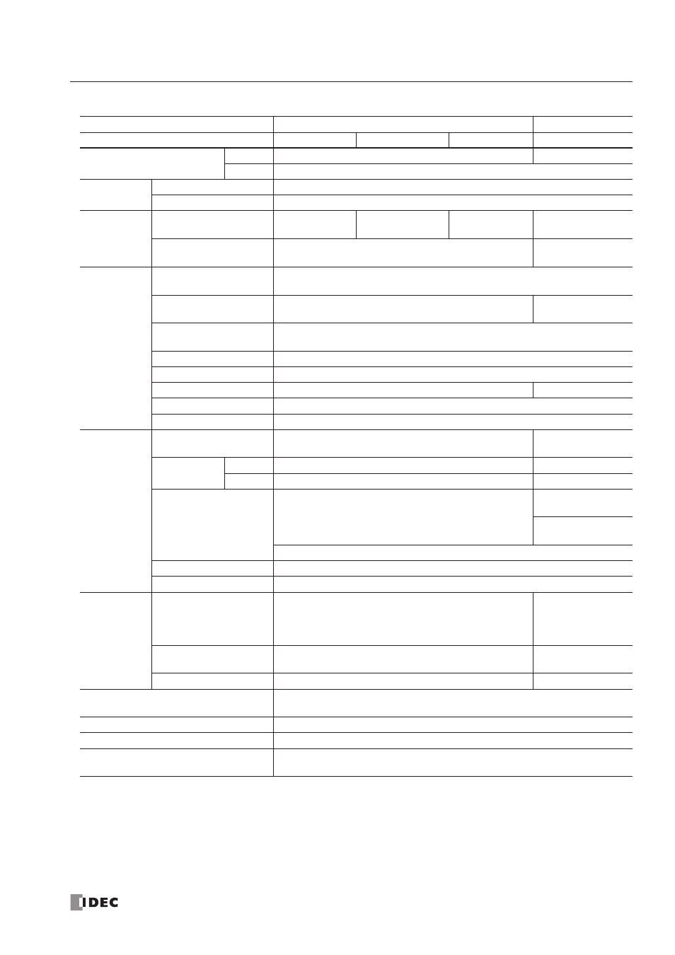
Analog Output Specifications
Note 1: Values in ( ) represent analog I/O modules earlier than version 200. For analog I/O module version, see page 2-44.
Note 2: The data processed in the analog I/O module can be linear-conver ted to a value between –32768 and 32767. The
optional range designation, and analog I/O data minimum and maximum values can be selected using data registers allo-
cated to analog I/O modules. See page 24-12.
Note 3: For analog I/O modules of version 200 or higher, the value represents when 1 kV is directly applied to the power
supply line and a 1 kV clamp voltage is applied to I/O lines. For analog I/O modules earlier than version 200, the value rep-
resents when a 500V clamp voltage is applied to the power supply and I/O lines.
Category
END Refresh Type
Ladder Refresh
Type No.
FC4A-L03A1
FC4A-L03AP1
FC4A-K1A1
FC4A-K2C1
Output Range
Voltage
0 to 10V DC
–10 to +10V DC
Current
4 to 20 mA DC
Load
Load Impedance
1 (2) k
Ω minimum (voltage), 300Ω maximum (current) (Note 1)
Applicable Load Type
Resistive load
DA
Conversion
Settling Time
10 (50) ms
(Note 1)
10 (130) ms
(Note 1)
10 (50) ms
(Note 1)
1 ms/ch
Total Output System
Transfer Time
Settling time + 1 scan time
1 ms
× channels
+ 1 scan time
Output Error
Maximum Error at
25°C
±0.2% of full scale
Temperature
Coefficient
±0.015% of full scale/°C
±0.005% of full
scale/°C
Repeatability after
Stabilization Time
±0.5% of full scale
Output Voltage Drop
±1% of full scale
Non-lineality
±0.2% of full scale
Output Ripple
1 LSB maximum
±0.1% of full scale
Overshoot
0%
Total Error
±1% of full scale
Data
Digital Resolution
4096 increments (12 bits)
50000 increments
(16 bits)
Output Value
of LSB
Voltage
2.5 mV
0.4 mV
Current
4 µA
0.32 µA
Data Type in
Application Program
Default: 0 to 4095 (voltage, current)
–25000 to 25000
(voltage)
0 to 50000
(current)
Optional: –32768 to 32767 (selectable for each channel) (Note 2)
Monotonicity
Yes
Current Loop Open
Not detectable
Noise
Resistance
Maximum Temporary
Deviation during
Electrical Noise Tests
(Note 3)
±1% (±3%) maximum (Note 1)
±3% maximum
Recommended Cable
for Noise Immunity
Twisted pair shielded cable
Twisted pair cable
Crosstalk
No crosstalk because of 1 channel output
2 LSB maximum
Isolation
Between input and power circuit:
Isolated
Between input and internal circuit:
Photocoupler-isolated
Effect of Improper Output Connection
No damage
Selection of Analog Output Signal Type
Using programming software
Calibration or Verification to Maintain
Rated Accuracy
Not possible