I/o c – IDEC MicroSmart User Manual
Page 392
24: A
NALOG
I/O C
ONTROL
24-6
« FC4A M
ICRO
S
MART
U
SER
’
S
M
ANUAL
»
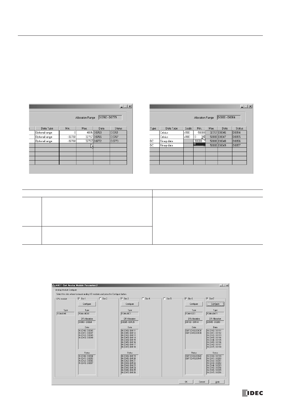
10. Select maximum and minimum values.
For analog input values, when Optional range is selected for the Data Type, designate the analog input data minimum and
maximum values which can be –32,768 through 32,767.
In addition, when using resistance thermometers (Pt100, Pt1000, Ni100, or Ni1000) with the Celsius or Fahrenheit Data
Type and the
×100 scale, select the analog input data minimum value from 0 or another value in the pull-down list. The
maximum value is changed automatically according to the selected minimum value.
For analog output values, when Optional range is selected for the Data Type, designate the analog output data minimum
and maximum values which can be –32,768 through 32,767.
11. View the data register numbers allocated to Data and Status.
12. Click the OK button to save changes and exit the Configure Parameter dialog box.
13. Repeat the same steps for other slots.
14. When finished, click the OK button to save changes and exit the Set Analog Module Parameters dialog box.
Parameter
DR Allocation
Data
Analog I/O Data
Stores the digital data conver ted from an analog input
signal or conver ted into an analog output signal.
Designated as source operand S4 (process variable)
of the PID instruction.
END Refresh Type
Data registers are automatically allocated depending
on the slot where the analog I/O module is mounted.
Ladder Refresh Type
Data registers are automatically allocated depending
on the number designated in the DR Allocation Num-
ber field.
Status
Analog I/O Operating Status
Stores an analog I/O operating status code.
See pages 24-13 and 24-15.