I/o wiring diagrams (all-in-one type cpu module), Odule, Pecifications – IDEC MicroSmart User Manual
Page 30: 10 « fc4a m, Dc source input wiring
2: M
ODULE
S
PECIFICATIONS
2-10
« FC4A M
ICRO
S
MART
U
SER
’
S
M
ANUAL
»
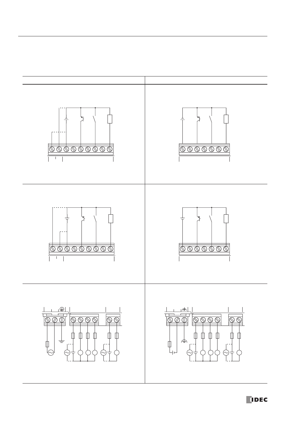
I/O Wiring Diagrams (All-in-One Type CPU Module)
The input and output wiring examples of the CPU modules are shown below. For wiring precautions, see pages 3-13
through 3-16.
AC Power Type CPU Module
DC Power Type CPU Module
DC Source Input Wiring
DC Source Input Wiring
DC Sink Input Wiring
DC Sink Input Wiring
AC Power and Relay Output Wiring
DC Power and Relay Output Wiring
+24V
0V
DC OUT
COM
DC IN
0
1
2
3
4
5
+
–
+
–
Sensor
External
Power
2-wire
Sensor
Power
+
–
+
–
External
Power
2-wire
COM
DC IN
0
1
2
3
4
5
Sensor
+24V
0V
DC OUT
COM
DC IN
0
1
2
3
4
5
+
–
+
–
Sensor
External
Power
2-wire
Sensor
Power
COM
DC IN
0
1
2
3
4
5
+
–
+
–
External
Power
2-wire
Sensor
L
N
100-240VAC
Ry.OUT
Ry.OUT
COM0
COM1 3
0
1
2
+
–
L
L
L
L
+
–
L
N
L
N
Fuse
Fuse
Load
Ry.OUT
Ry.OUT
COM0
COM1 3
0
1
2
+
–
24VDC
+
–
L
L
L
L
+
–
L
N
L
N
Fuse
Fuse
Load
+ –