IDEC MicroSmart User Manual
Page 166
6: A
LLOCATION
N
UMBERS
6-2
« FC4A M
ICRO
S
MART
U
SER
’
S
M
ANUAL
»
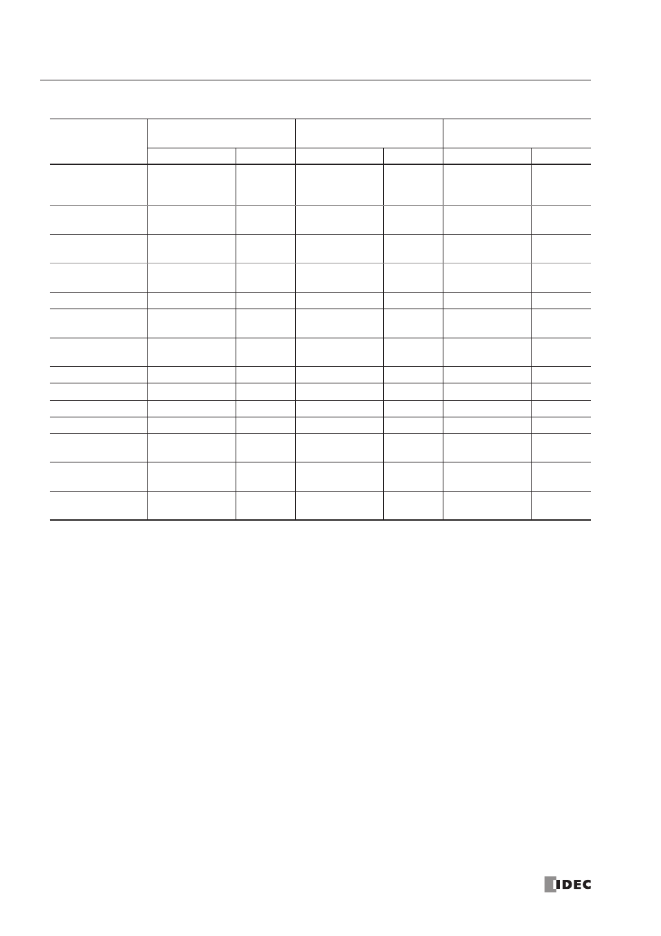
Slim Type CPU Modules
Notes:
•
The least significant digit of input, output, internal relay, and special internal relay operand number is an octal number (0
through 7). Upper digits are decimal numbers.
•
The allocation numbers of expansion inputs and outputs star t with I30 and Q30, respectively.
•
Note that input and output allocation numbers are not continuous between the CPU module and expansion I/O modules.
•
A maximum of 7 expansion I/O modules can be mounted on all slim type CPU modules. The maximum I/O points depend
on the CPU module type as described below.
•
The 20-I/O type CPU module (FC4A-D20K3 and FC4A-D20S3) can add a maximum of 128 I/O points, and use a maximum
of 148 points of inputs and outputs in total.
•
The 20-I/O relay output type CPU module (FC4A-D20RK1 and FC4A-D20RS1) can add a maximum of 224 I/O points, and
use a maximum of 244 points of inputs and outputs in total.
•
The 40-I/O type CPU module (FC4A-D40K3 and FC4A-D40S3) can add a maximum of 224 I/O points, and use a maximum
of 264 points of inputs and outputs in total.
•
Four models of the slim type CPU modules (FC4A-D20RK1, FC4A-D20RS1, FC4A-D40K3, and FC4A-D40S3) with system
program ver. 201 and higher can use the AS-Inter face master module, and have additional internal relays and data regis-
ters for AS-Inter face communication. Use WindLDR ver. 4.20 or higher to program the AS-Inter face operands. For details
about AS-Inter face communication, see a separate user’s manual for the AS-Inter face master module.
•
When the AS-Inter face master module is not connected, these AS-Inter face operands can be used for basic and advanced
instructions like ordinar y internal relays and data registers. Note that these operands cannot be designated for keep or
clear operands in the Function Area Settings dialog box in
WindLDR
. In addition, the clear operand data command of the
maintenance communication protocol and the designated reset input do not work on these AS-Inter face operands. The sta-
tuses of these AS-Inter face operands are maintained at power-up or when a reset input is turned on, but are cleared when
a keep data error occurs.
Operand
FC4A-D20K3
FC4A-D20S3
FC4A-D20RK1
FC4A-D20RS1
FC4A-D40K3
FC4A-D40S3
Allocation No.
Points
Allocation No.
Points
Allocation No.
Points
Input (I)
I0 - I7
I10 - I13
12
I0 - I7
I10 - I13
12
I0 - I7
I10 - I17
I20 - I27
24
Expansion Input (I)
I30 - I187
128
(140 total)
I30 - I307
224
(236 total)
I30 - I307
224
(248 total)
Output (Q)
Q0 - Q7
8
Q0 - Q7
8
Q0 - Q7
Q10 - Q17
16
Expansion
Output (Q)
Q30 - Q187
128
(136 total)
Q30 - Q307
224
(232 total)
Q30 - Q307
224
(240 total)
Internal Relay (M)
M0 - M1277
1024
M0 - M1277
1024
M0 - M1277
1024
AS-Interface
Internal Relay (M)
—
—
M1300 - M1997
560
M1300 - M1997
560
Special Internal
Relay (M)
M8000 - M8157
128
M8000 - M8157
128
M8000 - M8157
128
Shift Register (R)
R0 - R127
128
R0 - R127
128
R0 - R127
128
Timer (T)
T0 - T99
100
T0 - T99
100
T0 - T99
100
Counter (C)
C0 - C99
100
C0 - C99
100
C0 - C99
100
Data Register (D)
D0 - D1299
1300
D0 - D1299
1300
D0 - D1299
1300
AS-Interface Data
Register (D)
—
—
D1700 - D1999
300
D1700 - D1999
300
Expansion Data
Register (D)
—
—
D2000 - D7999
6000
D2000 - D7999
6000
Special Data
Register (D)
D8000 - D8199
200
D8000 - D8199
200
D8000 - D8199
200