IDEC MicroSmart User Manual
Page 135
5: S
PECIAL
F
UNCTIONS
« FC4A M
ICRO
S
MART
U
SER
’
S
M
ANUAL
»
5-15
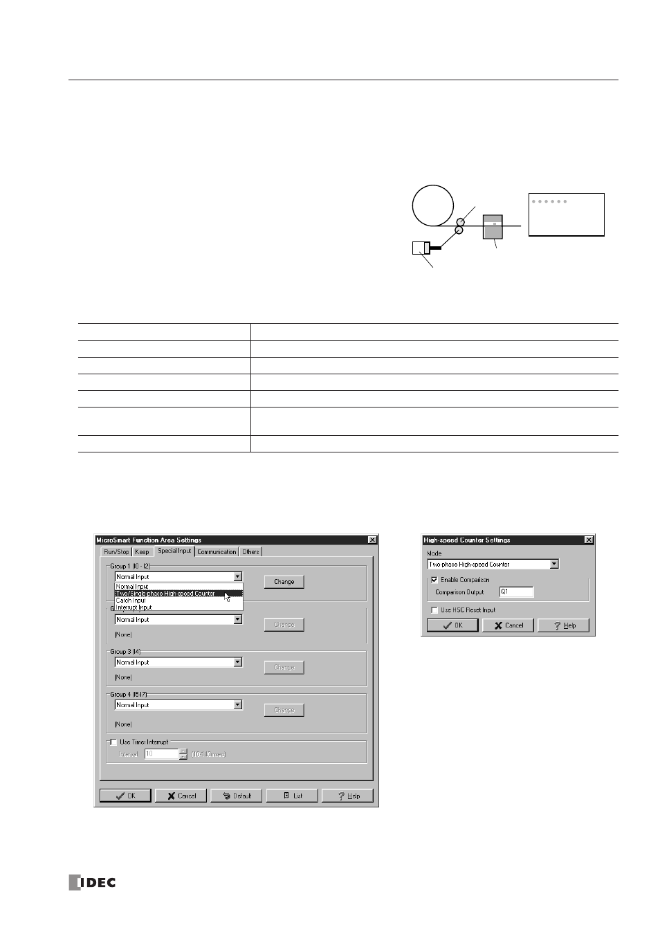
Example: Two-phase High-speed Counter for Counting Input Pulses from Rotary Encoder
This example demonstrates a program for two-phase high-speed counter HSC1 to punch holes in a paper tape at regular
intervals.
Description of Operation
A rotary encoder is linked to the tape feed roller directly, and
the output pulses from the rotary encoder are counted by the
two-phase high-speed counter in the
MicroSmart
CPU module.
When the high-speed counter counts 2,700 pulses, the compar-
ison output is turned on. When the comparison output is turned
on, the high-speed counter continues another cycle of counting.
The comparison output remains on for 0.5 second to punch
holes in the tape, and is turned off before the high-speed
counter counts 2,700 pulses again.
Program Parameters
Note: This example does not use the phase Z signal (input I2).
Programming WindLDR
Group 1 (I0 - I2)
Two/Single-phase High-speed Counter
High-speed Counter Settings
Two-phase High-speed Counter
Enable Comparison
Yes
Comparison Output
Q1
Use HSC Reset Input (I2)
No
HSC Reset Value (D8046)
To cause current value over flow ever y 2700 pulses, store 62836 to D8046
(65535 – 2700 + 1 = 62836)
Timer Preset Value
0.5 sec (needed for punching) programmed in TIM instruction
Feed Roller
Rotary Encoder
Tape Punch
Rolled Tape