Control circuit wiring, Control circuit terminal block functions, 6 control circuit wiring – Yaskawa iQpump Micro User Manual
Page 75: Input terminals, Output terminals
3.6 Control Circuit Wiring
u
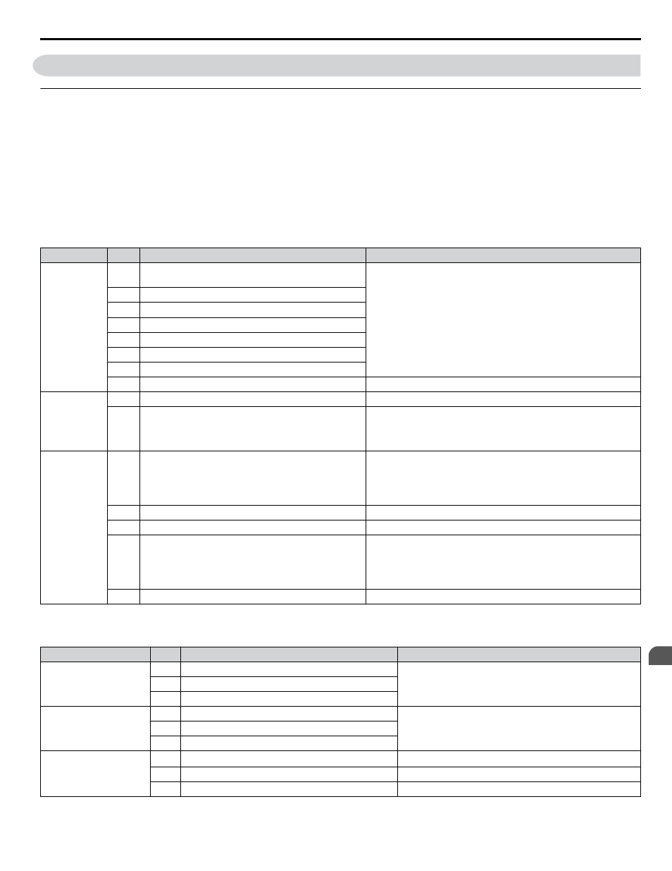
Control Circuit Terminal Block Functions
Drive parameters determine which functions apply to the multi-function digital inputs (S1 to S7), multi-function digital outputs
(MA, MB), multi-function pulse inputs and outputs (RP, MP) and multi-function photocoupler outputs (P1, P2). The default
is called out next to each terminal in
.
WARNING! Sudden Movement Hazard. Always check the operation and wiring of control circuits after being wired. Operating a drive with
untested control circuits could result in death or serious injury.
WARNING! Confirm the drive I/O signals and external sequence before starting test run. Setting parameter A1-06 may change the I/O
terminal function automatically from the factory setting. Failure to comply may result in death or serious injury.
n
Input Terminals
Table 3.8 Control Circuit Input Terminals
Type
No.
Terminal Name (Function)
Function (Signal Level) Default Setting
Multi-Function
Digital Inputs
S1
Multi-function input 1 (Closed: Forward run, Open:
Stop)
Photocoupler
24 Vdc, 8 mA
Note: Drive preset to sinking mode. When using source mode, set
DIP switch S3 to allow for a 24 Vdc (±10%) external power supply.
Refer to Sinking/Sourcing Mode Switch on page 79
for details.
S2
Multi-function input 2 (Not used/Through mode)
S3
Multi-function input 3 (External pump fault (N.O.)
S4
Multi-function input 4 (Fault reset)
S5
Multi-function input 5 (Multi-step speed reference 1)
S6
Multi-function input 6 (HAND Mode)
S7
Multi-function input 7 (HAND Mode 2)
SC
Multi-function input common (Control common)
Sequence common
Safe Disable
Input
HC
Power supply for safe disable input
+24 Vdc (max 10 mA allowed)
H1
Safe disable input
Open: Output disabled
Closed: Normal operation
Note: Disconnect wire jumper between HC and H1 when using the
safe disable input. The wire length should not exceed 30 m.
Main
Frequency
Reference
Input
RP
Multi-function pulse train input (frequency reference)
Response frequency: 0.5 to 32 kHz
(Duty Cycle: 30 to 70%)
(High level voltage: 3.5 to 13.2 Vdc)
(Low level voltage: 0.0 to 0.8 Vdc)
(input impedance: 3 kΩ)
+V
Analog input power supply
+10.5 Vdc (max allowable current 20 mA)
A1
Multi-function analog input 1 (frequency reference)
Input voltage 0 to +10 Vdc (20 kΩ) resolution 1/1000
A2
Multi-function analog input 2 (frequency reference)
Input voltage or input current (Selected by DIP switch S1 and H3-09)
0 to +10 Vdc (20 kΩ),
Resolution: 1/1000
4 to 20 mA (250 Ω) or 0 to 20 mA (250 Ω),
Resolution: 1/500
AC
Frequency reference common
0 Vdc
n
Output Terminals
Table 3.9 Control Circuit Output Terminals
Type
No.
Terminal Name (Function)
Function (Signal Level) Default Setting
Multi-Function Digital
Output
<1>
MA N.O. (Fault)
Digital output
30 Vdc, 10 mA to 1 A; 250 Vac, 10 mA to 1 A
Minimum load: 5 Vdc, 10 mA (reference value)
MB N.C. (Fault)
MC Digital output common
Multi-Function
Photocoupler Output
P1
Photocoupler output 1 (During run)
Photocoupler output 48 Vdc, 2 to 50 mA
<2>
P2
Photocoupler output 2 (Fault)
PC
Photocoupler output common
Monitor Output
MP Pulse train output (Output frequency)
32 kHz (max)
<3>
<4>
AM Analog monitor output
0 to 10 Vdc (2 mA or less) Resolution: 1/1000
AC Monitor common
0 V
<1> Do not assign functions to digital relay outputs that involve frequent switching. This may shorten relay performance life. Switching life is estimated
at 200,000 times (assumes 1 A, resistive load).
3.6 Control Circuit Wiring
YASKAWA TOEP YAIQPM 03B YASKAWA AC Drive - iQpump Micro User Manual
75
3
Electrical Installation