Yaskawa iQpump Micro User Manual
Page 131
Digital Input Function
Drive Operation
Input Open
Input Closed
Setting 8 (N.C.)
Baseblock (Interrupt output)
Normal operation
Setting 9 (N.O.)
Normal operation
Baseblock (Interrupt output)
WARNING! Sudden Movement Hazard. When using a mechanical holding brake with the drive in a lifting application, close the brake when
the drive output is cut off by a baseblock command triggered by one of the input terminals. Failure to comply will result in a slipping load
from the motor suddenly coasting when the baseblock command is entered and may cause serious injury or death.
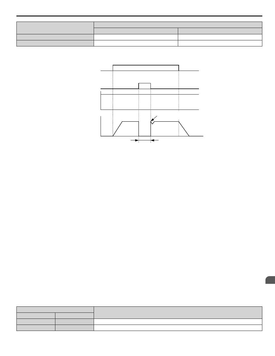
Begin Speed Search from the
previous frequency reference
Run command
Baseblock input
Frequency
reference
Output frequency
OFF
ON
Output off, motor coasts
ON
Baseblock
release
Figure 4.33 Baseblock Operation During Run
Setting A: Accel/Decel Ramp Hold
When the digital input programmed for the Accel/decel ramp hold function closes, the drive locks (holds) the output frequency.
Acceleration or deceleration resumes when the input is reopened.
If the Accel/decel ramp hold function is enabled (d4-01 = 1), the drive saves the output frequency to memory when the Ramp
Hold input is closed. When the drive is restarted after stop or after power supply interruption, the saved output frequency
becomes the frequency reference (provided that the Accel/decel ramp hold input is still closed).
Setting B: Drive Overheat Alarm (oH2)
Triggers an oH2 alarm when the contact closes. Drive operation is not affected because this is an alarm.
Setting C: Analog Terminal Input Selection (Terminal A1, A2)
When closed, the terminals specified in H3-14 are enabled. When open, the drive disregards the input signal to the analog
terminals.
Setting F: Not Used/Through Mode
Select this setting when using the terminal in a pass-through mode. When set to F, an input does not trigger any function in
the drive. Setting F, however, still allows the input status of the terminal (open or closed) to be read out by a PLC via a
communication option or MEMOBUS/Modbus communications. The drive input terminals can then be used as remote I/O by
the PLC.
Settings 10 and 11: Up/Down Function
The Up/Down function allows the frequency reference to be set by two push buttons when one digital input is programmed
as the Up input (H1-oo= 10) to increase the frequency reference and the other digital input is programmed as the Down input
(H1-oo= 11) to decrease the frequency reference.
The Up/Down function takes priority over the frequency references from the digital operator, the analog inputs, and the pulse
input (b1-01 = 0, 1, 4). When using the Up/Down function, references provided by these sources will be disregarded.
The inputs operate as shown in
Table 4.19 Up, Down Command
Status
Drive Operation
Up (10)
Down (11)
Open
Open
Hold current frequency reference
Closed
Open
Increase frequency reference
4.8 Detailed iQpump Parameter Descriptions
YASKAWA TOEP YAIQPM 03B YASKAWA AC Drive - iQpump Micro User Manual
131
4
Start-Up Programming & Operation