Figure 4.22 – Yaskawa iQpump Micro User Manual
Page 123
Drive
A1
A2
Frequency reference
Frequency reference bias
AC
Analog common
+V (+10.5 V, 20 mA power supply)
0 or 4 to 20 mA input
DIP switch S1
V
I
Figure 4.22 Setting the Frequency Reference by Current Input
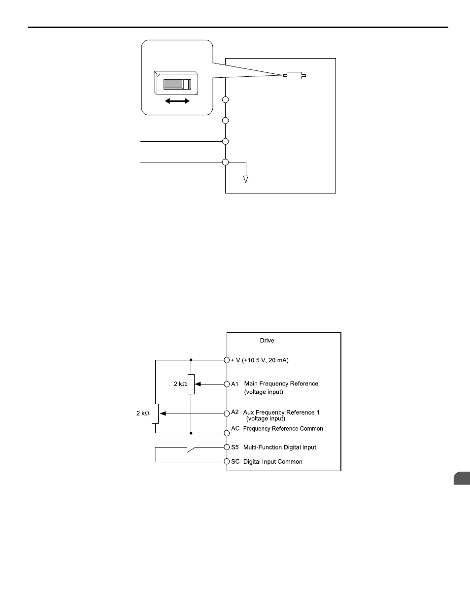
Switching between Main/Auxiliary Frequency References
The frequency reference input can be switched between terminal A1 (main) and terminal A2 (auxiliary). When using this
function:
• Make sure that b1-01 is set to “1” (Frequency reference from analog input).
• Set the terminal A2 function to auxiliary frequency (H3-10 = 2).
• Set one digital input to multi-speed 1 (H1-oo = 3, default for S5).
The frequency reference value is read from
• Terminal A1 when the digital input set for multi-speed 1 is open.
• Terminal A2 when the digital input set for multi-speed 1 is closed.
shows a wiring example for main/auxiliary reference switching using digital input S5.
Figure 4.23 Switching between Analog Reference 1 and 2
Setting 2: MEMOBUS/Modbus Communications
This setting requires entering the frequency reference via the RS-485/422 serial communications port (control terminals R+,
R-, S+, S-).
To setup the drive to receive the “Auto Setpoint” from serial communication, set b1-01 to “2: Serial Com,” and connect the
RS-422/RS-485 serial communications cable to terminals R+, R-, S+, and S- on the control I/O terminal block. Refer to
to see the connection diagram using a PC to provide the auto setpoint reference to the drive.
4.8 Detailed iQpump Parameter Descriptions
YASKAWA TOEP YAIQPM 03B YASKAWA AC Drive - iQpump Micro User Manual
123
4
Start-Up Programming & Operation