Yaskawa iQpump Micro User Manual
Page 137
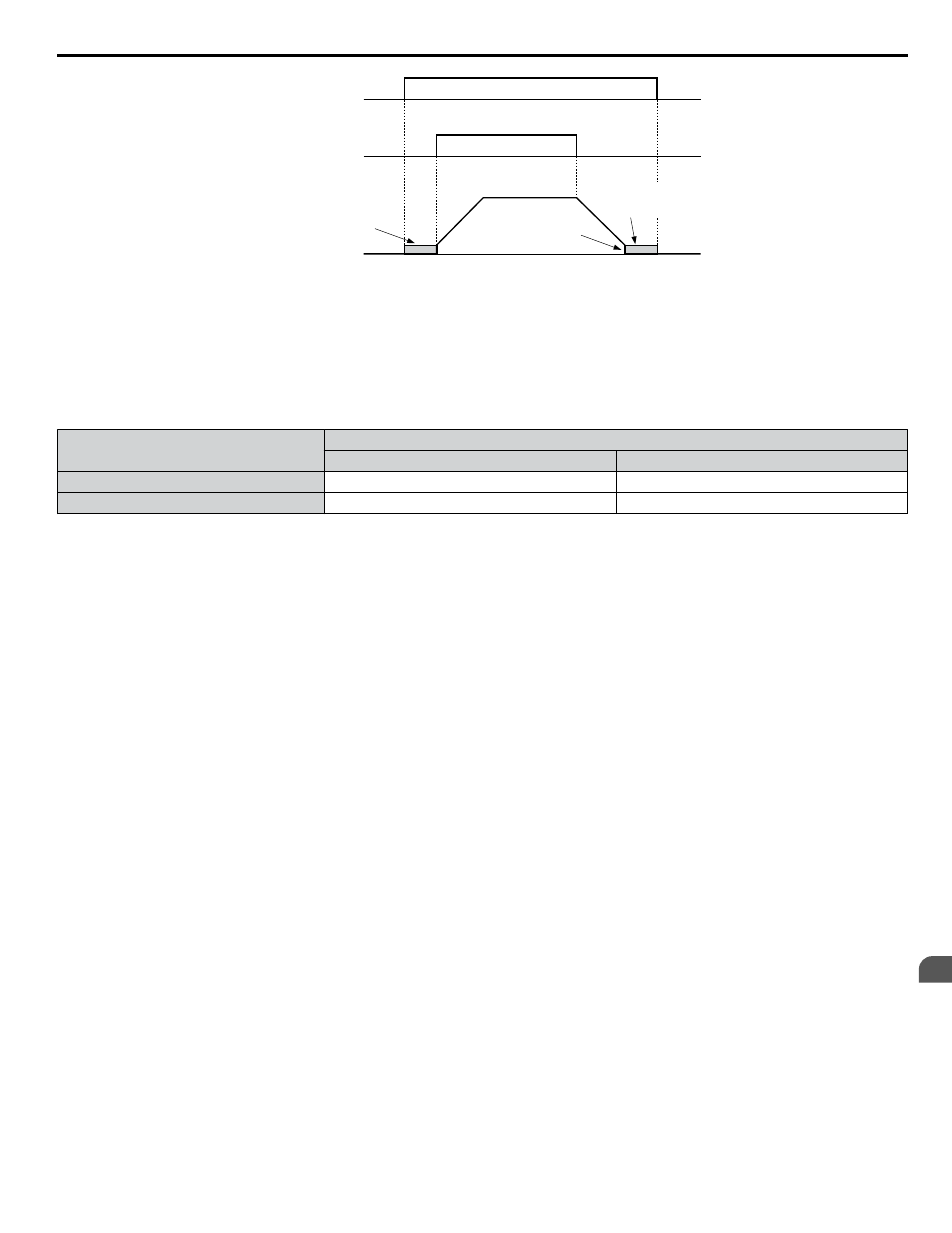
DC Injection braking
command
FWD Run command
Output frequency
DC Injection
braking
DC Injection
braking
DC Injection Braking
Start Frequency
(b2-01)
OFF
OFF
OFF
OFF
ON
ON
Figure 4.42 DC Injection Braking Input Timing Diagram
Settings 61 and 62: External Speed Search Command 1, 2
These input functions enable Speed Search even if parameter b3-01 = 0 (no Speed Search at start).
Note:
Assigning Speed Search 1 and Speed Search 2 to input terminals will trigger an oPE03 error.
Settings 65 and 66: KEB Ride-Thru 1 (N.C.), 2 (N.O.)
Enables the KEB Ride-Thru function selected in parameter L2-29.
Digital Input Function
Drive Operation
Input Open
Input Closed
Setting 65 (N.C.)
KEB Ride-Thru Deceleration
Normal operation
Setting 66 (N.O.)
Normal operation
KEB Ride-Thru Deceleration
Note:
Simultaneously assigning KEB Ride-Thru 1 and KEB Ride-Thru 2 to the input terminals will trigger an oPE03 error.
Setting 67: Communication Test Mode
The drive has a built-in function to self-diagnose serial communications operation. The test involves wiring the send and
receive terminals of the RS-422/RS-485 port together. The drive transmits data and then confirms that the communications
are received normally.
Setting 6A: Drive Enable
A digital input configured as a “Drive enable” (H1-oo = 6A) will prevent the drive from executing a Run command until
the input is closed. When the input is open, the digital operator will display “dnE” to indicate that the drive is disabled.
If a Run command is enabled before the terminal set for “Drive enable” closes, then the drive will not run until the Run
command is cycled (i.e., a new Run command is required). If the input is opened while the drive is running, the drive will stop
according to the stop method set to b1-03.
Refer to b1-03: Stopping Method Selection on page 125
Setting 73: Low City Press
Indicates that sufficient or insufficient pressure is present on the inlet to the pump. Used mainly for pressure booster situations.
Settings 75 and 76: Up 2/Down 2 Function
The Up/Down 2 function adds a bias to the frequency reference. The input programmed for 75 will increase the bias and the
input programmed for 76 will decrease the bias.
explains how the Up/Down 2 function works depending on the
frequency reference source and parameters d4-01, d5-03, and d4-05.
Note:
1. The Up/Down 2 functions must be set as a pair.
2. When using the Up/Down 2 function, set appropriate bias limit values to parameters d4-08 and d4-09.
4.8 Detailed iQpump Parameter Descriptions
YASKAWA TOEP YAIQPM 03B YASKAWA AC Drive - iQpump Micro User Manual
137
4
Start-Up Programming & Operation