Fault detection, Fault displays, causes, and possible solutions, 2 fault detection – Yaskawa iQpump Micro User Manual
Page 165
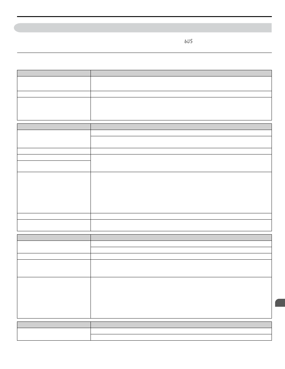
5.2 Fault Detection
Note:
Digital operator display text is represented in the tables below using standard font for both LCD displays and LED displays. When using
the standard LED operator, however, display text will appear in 7-segment LED (ex: “
”). When the LED fault display differs from the
LCD display, the LED display text will be shown in parentheses under the LCD display text.
u
Fault Displays, Causes, and Possible Solutions
Table 5.2 Detailed Fault Displays, Causes, and Possible Solutions
Digital Operator Display
Fault Name
AJF
Anti-Jam Fault
(AJF)
Anti-Jam Fault
Cause
Possible Solution
The drive was not able to clear debris from
the impeller in fewer than the number of
attempts set in P7-02. This is only effective
when P7-01, Anti-jam Operation is set to 1
(enabled).
• Check for proper pump operation. Remove debris from the pump impeller.
• Adjust the P7-03 level or the P7-02 counts.
• Drive response to this condition is controlled by P7-01, Anti-jam Operation Selection.
Digital Operator Display
Fault Name
bUS
Option Communication Error
• The connection was lost after establishing initial communication.
• Only detected when the run command frequency reference is assigned to an option card.
Cause
Possible Solution
No signal was received from the PLC
• Check for faulty wiring.
• Correct the wiring.
• Check for disconnected cables and short circuits and repair as needed.
Faulty communications wiring or an
existing short circuit
Communication data error occurred due to
noise
• Check the various options available to minimize the effects of noise.
• Counteract noise in the control circuit, main circuit, and ground wiring.
• Ensure that other equipment such as switches or relays do not cause noise. Use surge absorbers if
necessary.
• Use only recommended cables or other shielded line. Ground the shield on the controller side or the drive
input power side.
• Separate all communication wiring from drive power lines. Install an EMC noise filter to the drive power
supply input.
The option card is damaged
Replace the option card if there are no problems with the wiring and the error continues to occur.
The option card is not properly connected
to the drive
• The connector pins on the option card do not line up properly with the connector pins on the drive.
• Reinstall the option card.
Digital Operator Display
Fault Name
CE
MEMOBUS/Modbus Communication Error
Control data was not received for the CE detection time set to H5-09.
Cause
Possible Solution
Faulty communications wiring or an
existing short circuit
• Check for faulty wiring.
• Correct the wiring.
• Check for disconnected cables and short circuits and repair as needed.
Communication data error occurred due to
noise
• Check the various options available to minimize the effects of noise.
• Counteract noise in the control circuit, main circuit, and ground wiring.
• Use only recommended cables or other shielded line. Ground the shield on the controller side or the drive
input power side.
• Ensure that other equipment such as switches or relays do not cause noise. Use surge suppressors if
required.
• Separate all communication wiring from drive power lines. Install an EMC noise filter to the drive power
supply input.
Digital Operator Display
Fault Name
CPF02
A/D Conversion Error
An A/D conversion error or control circuit error occurred.
5.2 Fault Detection
YASKAWA TOEP YAIQPM 03B YASKAWA AC Drive - iQpump Micro User Manual
165
5
Troubleshooting