Yaskawa iQpump Micro User Manual
Page 185
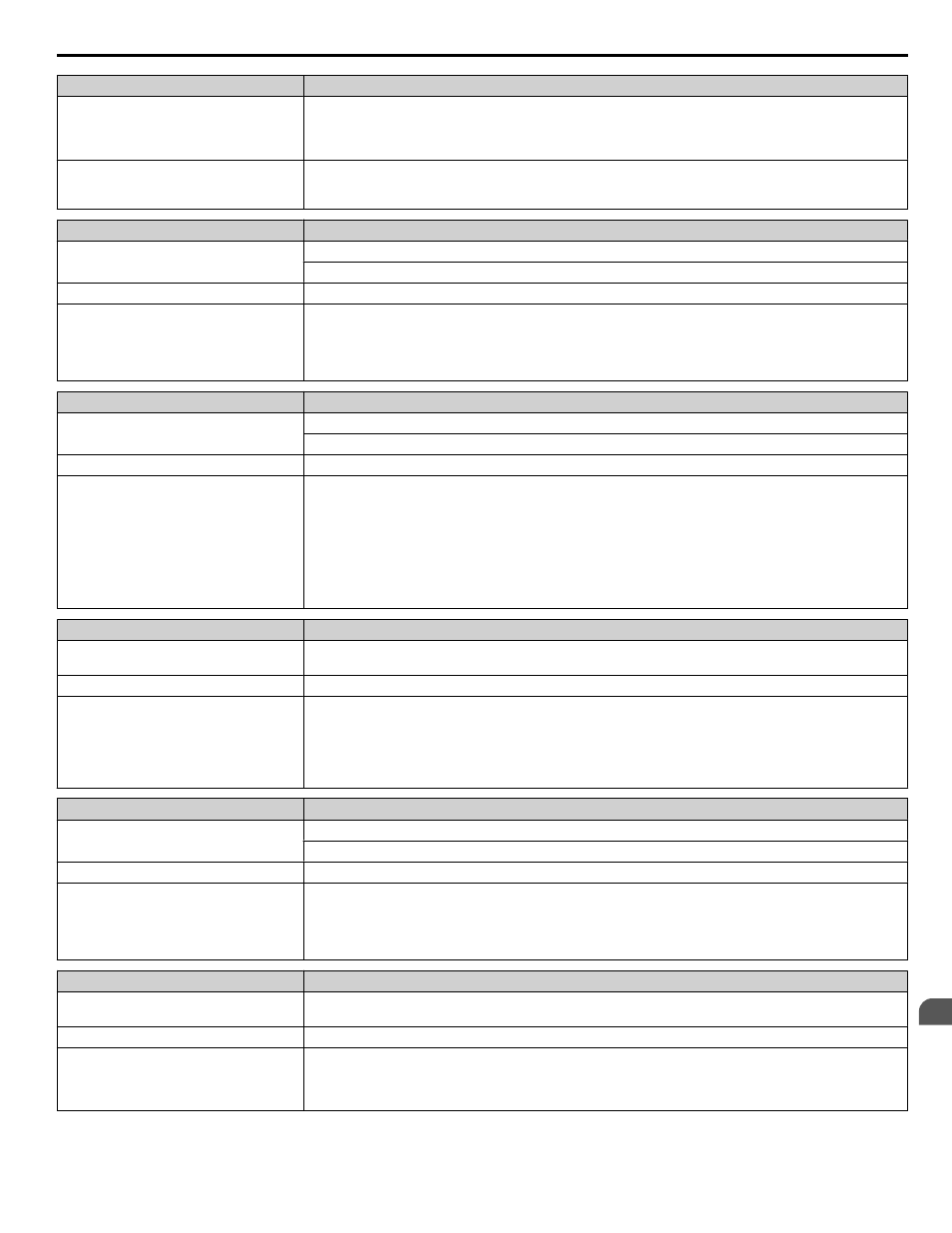
Digital Operator Display
Minor Fault Name
A special-purpose motor is being used, or
the drive is attempting to run a motor
greater than the maximum allowable
capacity.
• Check the motor capacity.
• Use a motor appropriate for the drive. Ensure the motor is within the allowable capacity range.
The current level increased due to Speed
Search after a momentary power loss or
while attempting to perform a fault restart.
The alarm will only appear briefly. There is no need to take action to prevent the alarm from occurring in
such instances.
Digital Operator Display
Minor Fault Name
High Feedback High FB Sensed
(HIFB)
High Feedback Level Alarm
The feedback signal is too high.
Cause
Possible Solutions
The feedback level has risen above the level
set in P1-11, High Feedback Level
This is only effective when P1-13, High
Feedback Selection, is set to 1 (Alarm and
digital out).
• Decrease the feedback signal.
• Set the High Feedback alarm characteristics in P1-11 and P-12.
• Drive response to this condition is controlled by P1-13, High Feedback Selection.
Digital Operator Display
Minor Fault Name
LOP
Loss of Prime
The pump has lost its prime and P1-22 is set to 1.
Cause
Possible Solution
The measured quantity of water has
dropped below the level set in P1-19, Prime
Loss Level, for the time set in P1-20, Loss
of Prime Time, and the output frequency
has risen above P1-21, Prime Loss
Frequency. This could be due to a dry well,
air in the system, or no water in the system.
This is effective only when P1-22 Loss of
Prime Selection is set to 1 (alarm).
• If there is resistance in the pump, allow the system to pump water again.
• Set the Loss of Prime alarm characteristics in P1-18, P1-19, P1-20, and P1-21.
• Drive response to this condition is controlled by P1-21, Loss of Prime Selection.
Digital Operator Display
Minor Fault Name
Low City Pressure
(LCP)
Low City Pressure
Cause
Possible Solution
Insufficient pressure is present on the inlet
to the pump.
Shown when P4-24 = 0 and when the digital
input has been active (closed for P4-21 = 0,
or open for P4-21 = 1) for the time set in
P4-22.
• Check pressure switch contact for correct operation.
• Check control wiring to drive terminal strip from pressure switch contact.
• Check to make sure that suction pressure is present by means of a separate measuring device.
Digital Operator Display
Minor Fault Name
Low Feedback Low FB Sensed
(LoFb)
Low Feedback Level Alarm
The feedback signal is too low.
Cause
Possible Solutions
The feedback level has dropped below the
level set in P1-08, Low Feedback Level
This is only effective when P1-10, Low
Feedback Selection, is set to 1 (Alarm and
digital out).
• Increase the feedback signal.
• Set the Low Feedback alarm characteristics in P1-08 and P1-09.
• Drive response to this condition is controlled by P1-10, Low Feedback Selection.
Digital Operator Display
Minor Fault Name
Low Suction Pressure
(LSP)
Low Suction Pressure
Cause
Possible Solution
Insufficient suction pressure is present.
Shown when P4-24 = 1 and when the digital input has been active (closed for P4-21 = 0, or open for P4-21
= 1) for the time set in P4-22.
The drive, if running, coasts-to-stop and does not run until the digital input has been inactive for the time
set in P4-22.
5.3 Alarm Detection
YASKAWA TOEP YAIQPM 03B YASKAWA AC Drive - iQpump Micro User Manual
185
5
Troubleshooting