SMA Sunny Data Control V.4.2 User Manual
Page 27
SMA
Technologie AG
Connecting the PC to a Communication Device
User Manual
SDC-TEN080642
Page 27
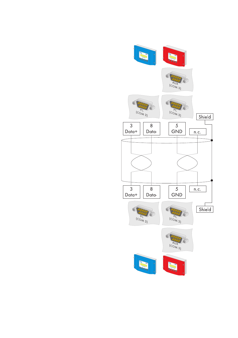
5.
Plug the 9-pin D-Sub female con-
nector into the port on the Sunny
Boy Control which is equipped
with the RS485 interface.
Sunny Boy Control: PC (COM 2)
Sunny Boy Control Plus: (COM 2)
or AUX (COM 3)
6.
Connect the PC's Data+ with the
Data+ of the Sunny Boy Control /
Plus, and so on. The 3 connections
should be made directly.
7.
At the last Sunny Boy Control /
Plus, jumper A must be mounted at
the port used. Jumper A must not
be mounted on any of the other
Sunny Boy Control / Plus devices.
Make sure that jumpers B and C
are not mounted at the port used.
8.
Connect the Data+ of the next Sun-
ny Boy Control / Plus with the Da-
ta+ of the Sunny Boy Control / Plus
which precedes it, and so on. The
3 connections are directly intercon-
nected.
9.
At the last Sunny Boy Control /
Plus, jumper A must be mounted at
the port used. Jumper A must not
be mounted on any of the other
Sunny Boy Control / Plus devices.
Make sure that jumpers B and C
are not mounted at the port used.
Sunny Boy Control Sunny Boy Control Plus
Sunny Boy Control Sunny Boy Control Plus