Configuration procedure – H3C Technologies H3C S12500 Series Switches User Manual
Page 291
275
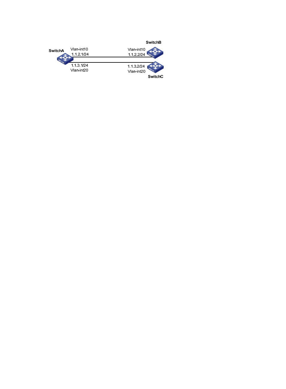
Figure 96 Network diagram
Configuration procedure
1.
Configure Switch A:
# Define ACL 3101 to match TCP packets.
[SwitchA] acl number 3101
[SwitchA-acl-adv-3101] rule permit tcp
[SwitchA-acl-adv-3101] quit
# Define Node 5 of policy aaa, which forwards TCP packets to next hop 1.1.2.2.
[SwitchA] policy-based-route aaa permit node 5
[SwitchA-pbr-aaa-5] if-match acl 3101
[SwitchA-pbr-aaa-5] apply ip-address next-hop 1.1.2.2
[SwitchA-pbr-aaa-5] quit
# Apply policy aaa to Switch A.
[SwitchA] ip local policy-based-route aaa
# Configure the IP addresses of VLAN-interface 10 and VLAN-interface 20.
[SwitchA] interface Vlan-interface 10
[SwitchA-Vlan-interface10] ip address 1.1.2.1 255.255.255.0
[SwitchA-Vlan-interface10] quit
[SwitchA] interface Vlan-interface 20
[SwitchA-Vlan-interface20] ip address 1.1.3.1 255.255.255.0
2.
Configure the IP address for VLAN-interface 10 on Switch B.
[SwitchB] interface Vlan-interface 10
[SwitchB-Vlan-interface10] ip address 1.1.2.2 255.255.255.0
[SwitchB-Vlan-interface10] quit
3.
Configure the IP address for VLAN-interface 20 on Switch C.
[SwitchC] interface Vlan-interface 20
[SwitchC-Vlan-interface20] ip address 1.1.3.2 255.255.255.0
[SwitchC-Vlan-interface20] quit
4.
Verify the configuration:
# Telnet to Switch B (1.1.2.2/24) from Switch A. The operation succeeds.
Trying 1.1.2.2 ...
Press CTRL+K to abort
Connected to 1.1.2.2 ...
******************************************************************************