Ospf graceful restart configuration example, Network requirements, Configuration procedure – H3C Technologies H3C S12500 Series Switches User Manual
Page 135
119
OSPF Graceful Restart configuration example
Network requirements
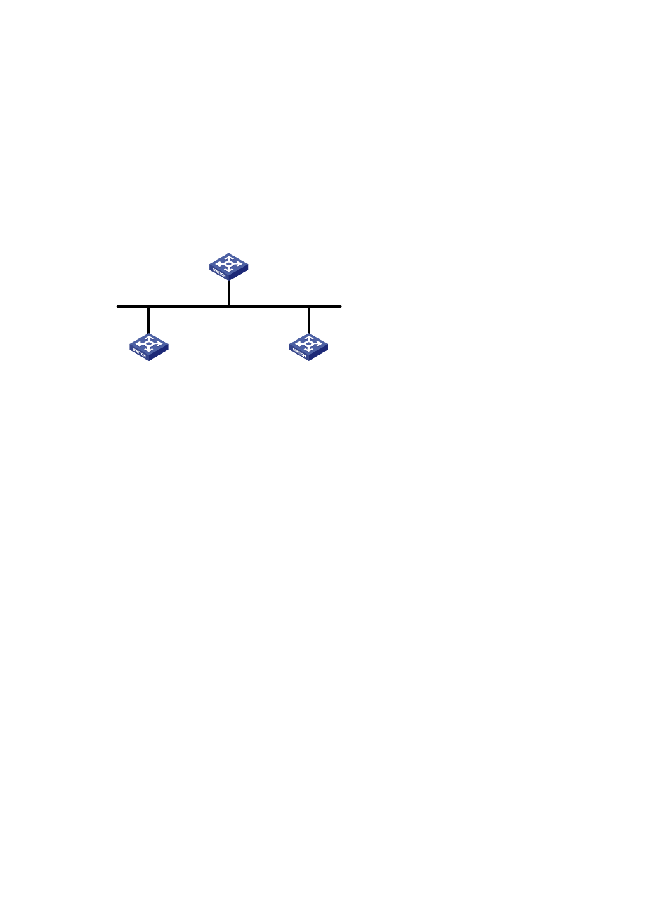
Switch A, Switch B and Switch C that belong to the same autonomous system and the same OSPF routing
domain are GR capable.
Switch A acts as the non-IETF standard GR restarter, whereas Switch B and Switch C are the GR helpers
and re-synchronize their LSDB with Switch A through OOB communication of GR.
Figure 47 Network diagram
Configuration procedure
1.
Configure IP addresses for interfaces. (Details not shown.)
2.
Configure basic OSPF:
# Configure Switch A
[SwitchA] router id 1.1.1.1
[SwitchA] ospf 100
[SwitchA-ospf-100] area 0
[SwitchA-ospf-100-area-0.0.0.0] network 192.1.1.0 0.0.0.255
[SwitchA-ospf-100-area-0.0.0.0] quit
# Configure Switch B
[SwitchB] router id 2.2.2.2
[SwitchB] ospf 100
[SwitchB-ospf-100] area 0
[SwitchB-ospf-100-area-0.0.0.0] network 192.1.1.0 0.0.0.255
[SwitchB-ospf-100-area-0.0.0.0] quit
# Configure Switch C
[SwitchC] router id 3.3.3.3
[SwitchC] ospf 100
[SwitchC-ospf-100] area 0
[SwitchC-ospf-100-area-0.0.0.0] network 192.1.1.0 0.0.0.255
[SwitchC-ospf-100-area-0.0.0.0] quit
3.
Configure OSPF GR:
Vlan-int100
192.1.1.1/24
Vlan-int100
192.1.1.3/24
Vlan-int100
192.1.1.2/24
GR helper
GR helper
GR restarter
Switch A
Switch C
Switch B
Router ID: 1.1.1.1
Router ID: 2.2.2.2
Router ID: 3.3.3.3