Configuration procedure – H3C Technologies H3C S12500 Series Switches User Manual
Page 267
251
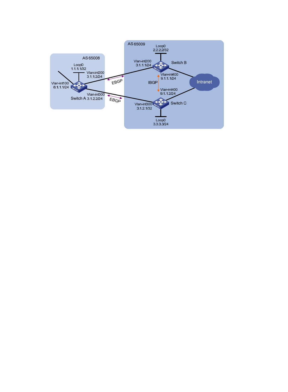
Figure 89 Network diagram
Configuration procedure
1.
Configure IP addresses for interfaces. (Details not shown.)
2.
Configure BGP connections:
{
On Switch A, establish EBGP connections with Switch B and Switch C; configure BGP to
advertise network 8.1.1.0/24 to Switch B and Switch C, so that Switch B and Switch C can
access the internal network connected to Switch A.
{
On Switch B, establish an EBGP connection with Switch A and an IBGP connection with Switch
C; configure BGP to advertise network 9.1.1.0/24 to Switch A, so that Switch A can access the
intranet through Switch B; configure a static route to interface loopback 0 on Switch C (or use
a routing protocol like OSPF) to establish the IBGP connection.
{
On Switch C, establish an EBGP connection with Switch A and an IBGP connection with Switch
B; configure BGP to advertise network 9.1.1.0/24 to Switch A, so that Switch A can access the
intranet through Switch C; configure a static route to interface loopback 0 on Switch B (or use
another protocol like OSPF) to establish the IBGP connection.
# Configure Switch A.
[SwitchA] bgp 65008
[SwitchA-bgp] router-id 1.1.1.1
[SwitchA-bgp] peer 3.1.1.1 as-number 65009
[SwitchA-bgp] peer 3.1.2.1 as-number 65009
[SwitchA-bgp] network 8.1.1.1 24
[SwitchA-bgp] quit
# Configure Switch B.
[SwitchB] bgp 65009
[SwitchB-bgp] router-id 2.2.2.2
[SwitchB-bgp] peer 3.1.1.2 as-number 65008
[SwitchB-bgp] peer 3.3.3.3 as-number 65009
[SwitchB-bgp] peer 3.3.3.3 connect-interface loopback 0
[SwitchB-bgp] network 9.1.1.0 255.255.255.0
[SwitchB-bgp] quit