Basic bgp configuration, Network requirements, Configuration procedure – H3C Technologies H3C S12500 Series Switches User Manual
Page 260
244
Basic BGP configuration
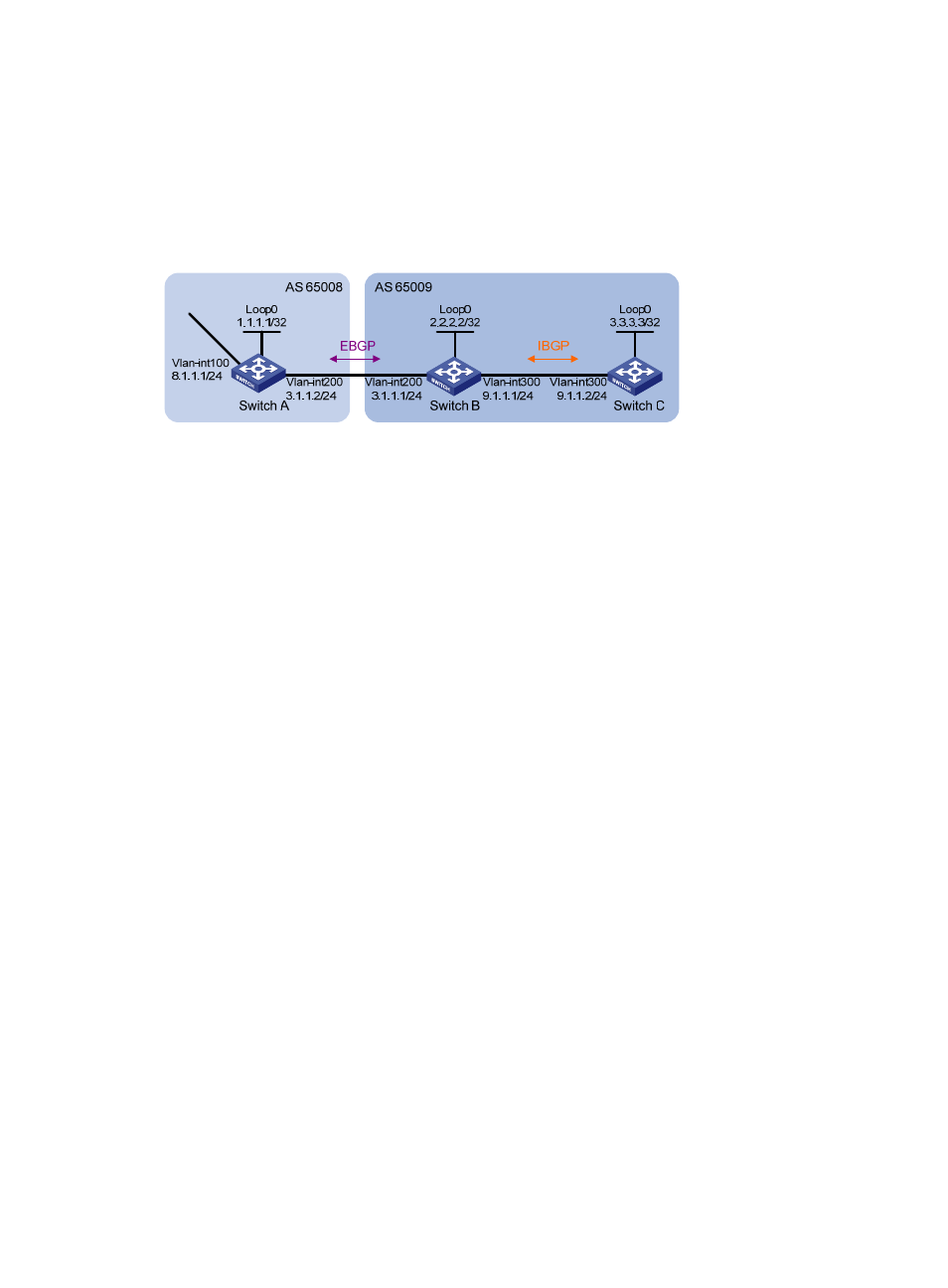
Network requirements
, run EBGP between Switch A and Switch B, and run IBGP between Switch B and Switch C
so that Switch C can access the network 8.1.1.0/24 connected to Switch A.
Figure 87 Network diagram
Configuration procedure
1.
Configure IP addresses for interfaces. (Details not shown.)
2.
Configure IBGP:
{
To prevent route flapping caused by port state changes, this example uses loopback interfaces
to establish IBGP connections.
{
Because loopback interfaces are virtual interfaces, use the peer connect-interface command to
specify the loopback interface as the source interface for establishing BGP connections.
{
Enable OSPF in AS 65009 to make sure that Switch B can communicate with Switch C through
loopback interfaces.
# Configure Switch B.
[SwitchB] bgp 65009
[SwitchB-bgp] router-id 2.2.2.2
[SwitchB-bgp] peer 3.3.3.3 as-number 65009
[SwitchB-bgp] peer 3.3.3.3 connect-interface loopback 0
[SwitchB-bgp] quit
[SwitchB] ospf 1
[SwitchB-ospf-1] area 0
[SwitchB-ospf-1-area-0.0.0.0] network 2.2.2.2 0.0.0.0
[SwitchB-ospf-1-area-0.0.0.0] network 9.1.1.1 0.0.0.255
[SwitchB-ospf-1-area-0.0.0.0] quit
[SwitchB-ospf-1] quit
# Configure Switch C.
[SwitchC] bgp 65009
[SwitchC-bgp] router-id 3.3.3.3
[SwitchC-bgp] peer 2.2.2.2 as-number 65009
[SwitchC-bgp] peer 2.2.2.2 connect-interface loopback 0
[SwitchC-bgp] quit
[SwitchC] ospf 1
[SwitchC-ospf-1] area 0