Sundance SMT712 User Manual
Page 79
User Manual SMT712
Page 79 of 89
Last Edited: 11/12/2012 10:36:00
4.6.3
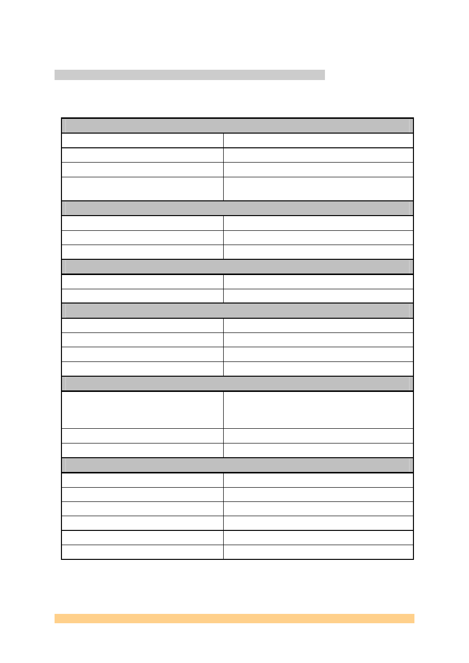
External Signal characteristics
The main characteristics of all external signals of the SMT712 are gathered into the
following table.
Analogue Outputs
Output voltage range
AC coupled option. AC coupled via RF transformer.
DACs Maximum Output Power
-2.6dBm (50R)
Impedance
50
Ω
.
Output Bandwidth
Minimum 1500MHz depending on the frequency
response mode set.
External Reference Input
Input Voltage Level
1-3.3 Volts peak-to-peak (AC-coupled)
Input Impedance
50
Ω
(Termination implemented at the connector)
Frequency Range
0 – 100 MHz.
External Reference Output
Output Voltage Level
1.6 Volts peak-to-peak (AC-coupled)
Output Impedance
50-Ohm (Termination implemented at the connector)
External Sampling Clock Input
Input Voltage Level
0.5 – 3.3 Volts peak-to-peak (AC-coupled)
Input Impedance
To be connected to a 50-Ohm source
Input Format
Single-ended.
Frequency range
960 (Firmware limitation)-2300 MHz
External Trigger Inputs
Input Voltage Level
0-3.3 Volts peak-to-peak (Schmidt Trigger).
Low : 0 -> 3.3/2 Volts
High : 3.3/2 -> 3.3Volts
Format
DC-coupled and Single-ended
Frequency range
Sampling Clock/8 maximum (MHz)
DACs Input Format
Input Data Width
12-Bits
Data Format
Offset Binary
SFDR
58-75dBs maximum (manufacturer fugures)
Wideband Noise-spectral Density
Up to -162dBm/Hz maximum (manufacturer figures)
Minimum Sampling Clock
10 MHz
Maximum Sampling Frequency
2300 MHz
Figure 17 – Main Characteristics.