Sundance SMT712 User Manual
Page 49
User Manual SMT712
Page 49 of 89
Last Edited: 11/12/2012 10:36:00
1
1
automatic reference switchover.
Setting
Bit 3
Description (Stay on REF2)
0
0
return to REF1 automatically when REF1 status is good again.
1
1
stay on REF2 after switchover. Do not automatically return to REF1.
Setting
Bit 2
Description (REF2 Power on)
0
0
REF2 power off.
1
1
REF2 power on.
Setting
Bit 1
Description (REF1 Power on)
0
0
REF1 power off.
1
1
REF1 power on.
Setting
Bit 0
Description (Differential Reference)
0
0
single-ended reference mode.
1
1
differential reference mode.
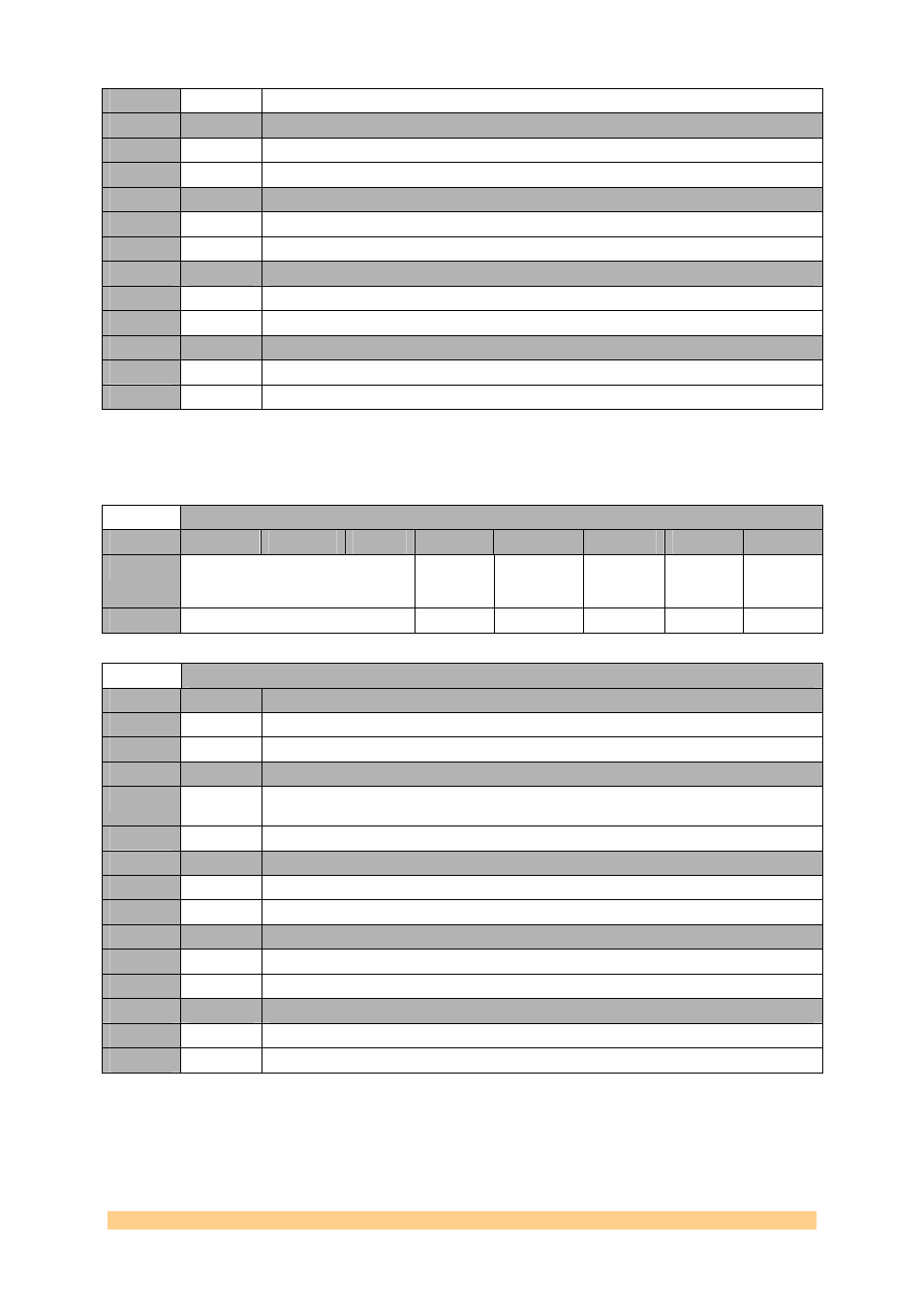
4.6.1.1.21
Clock Generator (AD9516-2) Register 0x1D – PLL Control
8 – 0xFC (write).
Clock Generator (AD9516-2) Register 0x1D – PLL Control 8 – 0xFC (write)
Byte
Bit 7
Bit 6
Bit 5
Bit 4
Bit 3
Bit 2
Bit 1
Bit 0
0
Reserved
PLL Status
Register
Disable
LD Pin
Comparator
Enable
Holdover
Enable
External
Holdover
Control
Holdover
Enable
Default
‘000’
‘0’
‘0’
‘0’
‘0’
‘0’
Clock Generator (AD9516-2) Register 0x1D – PLL Control 8 – 0xFC (write)
Setting
Bit 4
Description (PLL Status Register Disable)
0
0
PLL status register enable.
1
1
PLL status register disable.
Setting
Bit 3
Description (LD pin Comparator Enable)
0
0
disable LD pin comparator; internal/automatic holdover controller treats this pin as true
(high).
1
1
enable LD pin comparator.
Setting
Bit 2
Description (Holdover Enable)
0
0
holdover disabled.
1
1
holdover enabled.
Setting
Bit 1
Description (External Holdover Enable)
0
0
automatic holdover mode—holdover controlled by automatic holdover circuit.
1
1
external holdover mode—holdover controlled by SYNC pin.
Setting
Bit 0
Description (Holdover Enable)
0
0
holdover disabled.
1
1
holdover enabled.