Sundance SMT712 User Manual
Page 64
User Manual SMT712
Page 64 of 89
Last Edited: 11/12/2012 10:36:00
4.6.1.1.48
Clock Generator (AD9516-2) Register 0x193 – Divider1 –
0x16C (write).
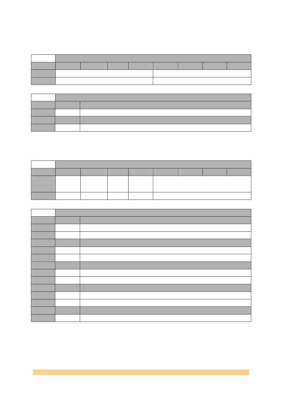
Clock Generator (AD9516-2) Register 0x193 – Divider1 – 0x16C (write)
Byte
Bit 7
Bit 6
Bit 5
Bit 4
Bit 3
Bit 2
Bit 1
Bit 0
0
Divider Low Cycles
Divider High Cycles
Default
‘0000’
‘0000’
Clock Generator (AD9516-2) Register 0x193 – Divider1 – 0x16C (write)
Setting
Bit 7..4
Description (Divider Low Cycles)
0
Number of clock cycles of the divider input during which divider output stays low.
Setting
Bit 3..0
Description (Divider High Cycles)
0
Number of clock cycles of the divider input during which divider output stays high.
4.6.1.1.49
Clock Generator (AD9516-2) Register 0x194 – Divider1 –
0x170 (write).
Clock Generator (AD9516-2) Register 0x194 – Divider1 – 0x170 (write)
Byte
Bit 7
Bit 6
Bit 5
Bit 4
Bit 3
Bit 2
Bit 1
Bit 0
0
Divider
bypass
Divider
Nosync
Divider
Force
High
Divider
Start High
Divider Phase Offset
Default
‘1’
‘0’
‘0’
‘0’
‘0000’
Clock Generator (AD9516-2) Register 0x194 – Divider1 – 0x170 (write)
Setting
Bit 7
Description (Divider Bypass)
0
0
use divider.
1
1
bypass divider.
Setting
Bit 6
Description (Divider Nosync)
0
0
obey chip-level SYNC signal.
1
1
ignore chip-level SYNC signal.
Setting
Bit 5
Description (Divider Force High)
0
0
divider output forced to low.
1
1
divider output forced to high.
Setting
Bit 4
Description (Divider Start High)
0
0
start low.
1
1
start high.
Setting
Bit 3..0
Description (REF2 Frequency Threshold)
0
0
Phase offset.