2 set control register – 0x10 (write) – Sundance SMT712 User Manual
Page 35
User Manual SMT712
Page 35 of 89
Last Edited: 11/12/2012 10:36:00
1
1
Over Temperature lower threshold reached.
Setting
Bit 31
Description – DACA or DACB DCM Busy Status
0
0
Normal Mode of Operation.
1
1
Either DACA DCM or DACB DCM is busy changing the value of the delay.
4.6.1.1.2
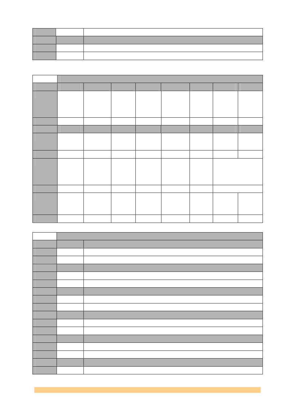
Set Control Register – 0x10 (write).
Offset 0x0400 -
Reset Register – 0x10 (write)
Byte
Bit 7
Bit 6
Bit 5
Bit 4
Bit 3
Bit 2
Bit 1
Bit 0
3
DDS /
DDR2
Pattern
Generator
Start/nStop
DACA
sampling
clock
cancel
cycle
DCM
DACB
Force
Reset
DCM
DACA
Force
Reset
Default
‘0’
‘0’
‘0’
‘0’
‘0’
‘0’
‘0’
‘0’
Byte
Bit 7
Bit 6
Bit 5
Bit 4
Bit 3
Bit 2
Bit 1
Bit 0
2
System
Monitor
Reset
SHB2
Reset
SHB1
Reset
DDR2 Reset
External
Trigger
Selection
Default
‘1’
‘0’
‘1’
‘1’
‘1’
‘0’
‘0’
‘0’
1
On-board
clock
synch
(active
low)
On-board
clock reset
and power
down
Reference
Clock
OnBoard
Divider
Reference
Clock Out
Divider
Soft Reset
Ref
Clock
Circuitry
Reset
Ref Clock Selection
Default
‘1’
‘1’
‘0’
‘0’
‘1’
‘1’
‘00’
0
Sampling
Clock
Selection
Source
CLOCK
Power
Supplies
Enable
DACB
Power
Supplies
Enable
DACA
Power
Supplies
Enable
DAC Reset
Clock
Update
(auto-
clear)
DACB
Update
(auto-
clear)
DACA
Update
(auto-
clear)
Default
‘0’
‘0’
‘0’
‘0’
‘1’
‘0’
‘0’
‘0’
Offset 0x0400 -
Reset Register – 0x10 (write)
Setting
Bit 0
Description – DACA Update (do not Auto-Clear)
0
0
Normal Mode of Operation
1
1
All Current ADCA Register are passed from the FPGA to the ADCA Chip
Setting
Bit 1
Description – DACB Update (do not Auto-Clear)
0
0
Normal Mode of Operation
1
1
All Current ADCB Register are passed from the FPGA to the ADCB Chip
Setting
Bit 2
Description – Clock Update (do not Auto-Clear)
0
0
Normal Mode of Operation
1
1
All Current Clock Register are passed from the FPGA to the Clock Chip
Setting
Bit 3
Description – DACs Reset (does not Auto-Clear)
0
0
Normal Mode of Operation
1
1
DACs in Reset mode (does not auto-clear)..
Setting
Bit 4
Description – DACA power supply.
0
0
DACA not powered.
1
1
DACA under power.
Setting
Bit 5
Description – DACB power supply.
0
0
DACB not powered.